Table of Contents
Advertisement
Quick Links
Industrial Device Server User's Manual
IDS-5042-WG / 5042-IWG Series
Version 1.0
May 2008.
ORing Industrial Networking Corp.
4F., NO.3, Lane235, Baociao Rd.Sindian City,
Taipei County 23145 Taiwan, R.O.C.
Tel:
+ 886 2 2918 3036
Fax:+ 886 2 2918 3084
Website :
www.oring-networking.com
E-mail :
support@oring-networking.com
Advertisement
Table of Contents

Related Manuals for ORiNG IDS-5042-WG Series


Summary of Contents for ORiNG IDS-5042-WG Series
- Page 1 Industrial Device Server User’s Manual IDS-5042-WG / 5042-IWG Series Version 1.0 May 2008. ORing Industrial Networking Corp. 4F., NO.3, Lane235, Baociao Rd.Sindian City, Taipei County 23145 Taiwan, R.O.C. Tel: + 886 2 2918 3036 Fax:+ 886 2 2918 3084 Website : www.oring-networking.com...
-
Page 2: Table Of Contents
Table of Content ....................1 ETTING TO EVICE ERVER About the IDS-5042-WG / 5042-IWG Serial Device Server ..............1 Software Features ..........................1 Hardware Features ...........................2 ........................3 ARDWARE NSTALLATION Install IDS-5042-WG / 5042-IWG on DIN-Rail ..................3 2.1.1 Mount IDS-5042-WG / 5042-IWG on DIN-Rail................3 Wall Mounting Installation .........................4 2.2.1 Mount IDS-5042-WG / 5042-IWG on wall ..................5... - Page 3 IDS-5042-WG Series User’s Manual 5.2.1.3 Management ........................50 5.2.1.4 Save/Reboot........................54 Configuration by SSH Console .......................55 5.3.1 Connect to DS..........................55 ......................... 56 ECHNICAL PECIFICATIONS...
-
Page 5: Getting To Know Your Device Server
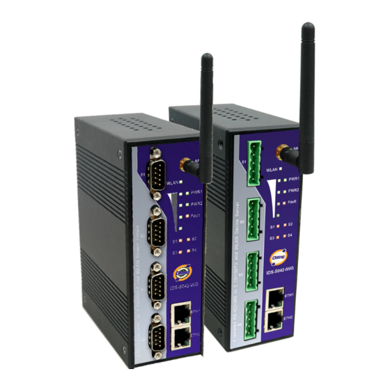
IDS-5042-WG Series User’s Manual etting to Know Your Device Server About the IDS-5042-WG / 5042-IWG Serial Device Server IDS-5042-WG / 5042-IWG is an innovative 4 ports RS232/422/485 to 802.11b/g WLAN and 2 ports LAN device server. Users are able to configure the Switch by DS-Tool via LAN port or WLAN interface, but not simultaneously. -
Page 6: Hardware Features
IDS-5042-WG Series User’s Manual Switch Mode Supported: Daisy Chain support to reduce usage of switch ports. High Speed Air Connectivity: WLAN interface support up to 54Mbps link speed NAT-pass through: User can manage IDS-5042-WG / 5042-IWG through NAT router. Highly Security Capability: WEP/WPA/WPA2/TKIP supported Redundant Power Inputs: 12~48VDC on terminal block. -
Page 7: Hardware Installation
IDS-5042-WG Series User’s Manual ardware Installation Install IDS-5042-WG / 5042-IWG on DIN-Rail Each IDS-5042-WG / 5042-IWG has a Din-Rail kit on rear panel. The Din-Rail kit helps IDS-5042-WG / 5042-IWG to fix on the Din-Rail. It is easy to install the IDS-5042-WG / 5042-IWG on the Din-Rail: 2.1.1 Mount IDS-5042-WG / 5042-IWG on DIN-Rail... -
Page 8: Wall Mounting Installation
IDS-5042-WG Series User’s Manual Step 2: Push the IDS-5042-WG / 5042-IWG toward the Din-Rail until you heard a “click” sound. Figure 2-2 Wall Mounting Installation Each IDS-5042-WG / 5042-IWG has another installation method for you. A wall mount panel can be found in the package. The following steps show how to mount the IDS-5042-WG /... -
Page 9: Mount Ids-5042-Wg / 5042-Iwg On Wall
IDS-5042-WG Series User’s Manual 2.2.1 Mount IDS-5042-WG / 5042-IWG on wall Step 1: Remove Din-Rail kit. Figure 2-3 ORing Industrial Networking Corp. - Page 10 IDS-5042-WG Series User’s Manual Step 2: Use 6 screws that can be found in the package to combine the wall mount panel. Just like the picture shows below: Figure 2-4 The screws specification shows in the following two pictures. In order to prevent IDS-5042-WG / 5042-IWG from any damage, the size of screws should not be larger than the size that used in IDS-5042-WG / 5042-IWG.
- Page 11 IDS-5042-WG Series User’s Manual Step 3: Mount the combined IDS-5042-WG / 5042-IWG on the wall. . Figure 2-6 ORing Industrial Networking Corp.
-
Page 12: Hardware Overview
IDS-5042-WG Series User’s Manual ardware Overview Front Panel Figure 3-1 1. LED for PWR1 and system status. When the PWR1 links, the green LED will be light on. 2. LED for PWR2 and system status. When the PWR2 links, the green LED will be light on. -
Page 13: Front Panel Leds
IDS-5042-WG Series User’s Manual 6. 10/100Base-T(X) Ethernet port 7. LED of 100Base-TX connection on Ethernet port. 8. RS-232/422/485 serial port. Mode configured by DS-Tool. 9. RS-422/485 serial port with 2KV isolation. Mode configured by DS-Tool. 10. Reverse SMA antenna connector. -
Page 14: Serial Ports
IDS-5042-WG Series User’s Manual Green On/Blinking 100Mbps LNK/ACT ETH2 Green/Amber Amber On/Blinking 10Mbps LNK/ACT WLAN Green On/Blinking WLAN LNK/ACT 4 / 3 / 2 / 1 / 0 LED(s) will be light on correspond to WLAN signal strength 100% / 75% / 50% /... -
Page 15: Bottom Panel
IDS-5042-WG Series User’s Manual 5 Pin Terminal block connector RS 485 RS 485 Pin # RS 422 ( 4 wire ) ( 2 wire ) RXD - RXD - RXD + RXD + TXD - TXD - DATA - TXD +... -
Page 16: Rear Panel
IDS-5042-WG Series User’s Manual Rear Panel The rear panel components of IDS-5042-WG / 5042-IWG are showed as below: 1. Screw holes for wall mount kit. 2. Din-Rail kit Figure 3-3 Rear Panel ORing Industrial Networking Corp... -
Page 17: Cables
IDS-5042-WG Series User’s Manual ables Ethernet Cables The IDS-5042-WG / 5042-IWG has standard Ethernet ports. According to the link type, the IDS-5042-WG / 5042-IWG use CAT 3, 4, 5,5e UTP cables to connect to any other network device (PCs, servers, switches, routers, or hubs). Please refer to the following table for cable specifications. - Page 18 IDS-5042-WG Series User’s Manual Pin Number Assignment Not used Not used Not used Not used Table 4-2 RJ-45 Pin Assignments The IDS-5042-WG / 5042-IWG supports auto MDI/MDI-X operation. You can use a straight- through cable to connect PC to IDS-5042-WG / 5042-IWG. The following table below shows the 10BASE-T/ 100BASE-TX MDI and MDI-X port pin outs.
-
Page 19: Management Interface
IDS-5042-WG Series User’s Manual anagement Interface DS-Tool DS-Tool is a powerful Windows utility for DS series. It supports device discovery, device configuration, group setup, group firmware update, monitoring functions...etc. It is easy for you to install and configure devices over the network. - Page 20 IDS-5042-WG Series User’s Manual Step 2: When installation complete successfully, then click “OK”. Figure 5-2 Step 3: Check for your selection. Figure 5-3 ORing Industrial Networking Corp...
-
Page 21: Using Ds-Tool
IDS-5042-WG Series User’s Manual 5.1.2 Using DS-Tool 5.1.2.1 Explore device servers DS-Tool will broadcast to the network and search all available DS devices in the network. The default IP address of device is “192.168.10.2”, and selects the searching device you wish to use and press “Add” button. -
Page 22: Configure Device Servers
IDS-5042-WG Series User’s Manual 5.1.2.2 Configure device servers General settings This page includes the setting of device name, SNTP server and Auto IP Report. Figure 5-5 General settings The following table describes the labels in this screen. Label Description You can set the device name or related information. By clicking “Locate On” button you Device Name/location can locate the serial server’s position. - Page 23 IDS-5042-WG Series User’s Manual By Clicking the “Get current Host” button you will get your local IP, and then set the Set Auto IP Report Report interval time. The device server will report its status periodically. Table 5-1 General settings At IP collection option show the device server status.
- Page 24 IDS-5042-WG Series User’s Manual Network Setting Device DS can connect the Network by wire and wireless. You must assign a valid IP address for DS before attached in your network environment. Your network administrator should provide you the IP address and related settings. The IP address must be unique within the network (otherwise, DS will not have a valid connection to the network).
- Page 25 IDS-5042-WG Series User’s Manual The following table describes the labels in this screen. Label Description Using DHCP/BOOTP IP Address automatically assigned by a DHCP server in your network. Static IP Address Manually assigning an IP address. All devices on the network must have the same subnet mask to communicate on the Subnet Mask network.
- Page 26 IDS-5042-WG Series User’s Manual Figure 5-8 Wireless Network Setting The following table describes the labels in this screen. Label Description Network Type Type includes INFRA and ADHOC. Service Set Identifier Default is the default setting. The SSID is a unique name that SSID identifies a network.
- Page 27 IDS-5042-WG Series User’s Manual Notification Specify the events that should be notified to the administrator. The events can be alarmed by E-mail, SNMP trap, or system log. Figure 5-9 Notification The following table describes the labels in this screen. Label...
- Page 28 IDS-5042-WG Series User’s Manual Management Figure 5-10 Management The following table describes the labels in this screen. Label Description To enable management from Web. Click “Goto Web Management” button to Web Management Enable access web. To enable management by Telnet. Click “Goto Telnet Management” button to Telnet Management Enable execute Telnet command.
- Page 29 IDS-5042-WG Series User’s Manual Upgrade Firmware Figure 5-11 Upgrade Firmware The following table describes the labels in this screen. Label Description Browsing Browse the file and upgrade Upgrade Enable the firmware upgrade. Table 5-6 Upgrade Firmware Save/Load Figure 5-12 Save / Load The following table describes the labels in this screen.
-
Page 30: Configure Serial Port
IDS-5042-WG Series User’s Manual Load default configuration except the network settings. If you want to load all factory Load Default default, you need to press “Reset” button on the device (Hardware restore). Reboot Device Reboot the device server (warm start). - Page 31 IDS-5042-WG Series User’s Manual The following table describes the labels in this screen. Label Description Port Alias Remark the port to hint the connected device. Interface RS232 / RS422 / RS485(2-wires) / RS485(4-wires) 110bps/300bps/1200bps/2400bps/4800bps/9600bps/19200bps/ Baud rate 38400bps/57600bps/115200bps/230400bps/460800bps Data Bits 5, 6, 7, 8 Stop Bits 1, 2 (1.5)
- Page 32 IDS-5042-WG Series User’s Manual Force TX interval time is to specify the timeout when no data has been transmitted. Force TX Interval Time When the timeout is reached or TX buffer is full (4K Bytes), the queued data will be sent.
- Page 33 IDS-5042-WG Series User’s Manual The following table describes the labels in this screen. Label Description Map Virtual COM Select a Virtual COM Name to map on. The number of Max connection can support simultaneous connections are 5, default Max Connection values is 1.
- Page 34 IDS-5042-WG Series User’s Manual Figure 5-13 TCP Server mode The following table describes the labels in this screen. Label Description Data Port Set the port number for data transmission. Auto Scan Scan the data port automatically. When serial port stops data transmission for a defined period of time (Idle Timeout), the connection will be closed and the port will be freed and try to connect with other hosts.
- Page 35 IDS-5042-WG Series User’s Manual Service Mode – TCP Client Mode In TCP Client Mode, device can establish a TCP connection with server by the method you have settled (Startup or any character). After the data has been transferred, device can disconnect automatically from the server by using the TCP alive check time or Idle time settings.
- Page 36 IDS-5042-WG Series User’s Manual When serial port stops data transmission for a defined period of time (Idle Timeout), the connection will be closed and the port will be freed and try to Idle Timeout connect with other hosts. 0 indicate disable this function. Factory default value is 0.
- Page 37 IDS-5042-WG Series User’s Manual Figure 5-15 UDP mode Notification Specify the events that should be noticed. The events can be noticed by E-mail, SNMP trap or system log. ORing Industrial Networking Corp.
- Page 38 IDS-5042-WG Series User’s Manual Figure 5-16 Notification The following table describes the labels in this screen. Label Description When DCD (Data Carrier Detect) signal changes, it indicates that the modem DCD changed connection status has changed. Notification will be sent.
-
Page 39: Configuration By Web Browser
IDS-5042-WG Series User’s Manual In TCP Server/Client Mode, when the device lost the TCP link, this event will be trigger. Port disconnected In Virtual COM Mode, When Virtual COM is not available, this event will be trigger. A notification will be sent. - Page 40 IDS-5042-WG Series User’s Manual Step 3: Input the name and password, then click “OK”. Figure 5-18 Certificate *Only if password is set. Step 4: The system information will be shown as below. Figure 5-19 System information ORing Industrial Networking Corp...
-
Page 41: System
IDS-5042-WG Series User’s Manual 5.2.1.1 System Time (SNTP) Figure 5-20 Time (SNTP) The following table describes the labels in this screen. Label Description Name You can set the name of DS. SNTP Enable the SNTP server. Time zone After you set the SNTP enable, select the time zone you located. - Page 42 IDS-5042-WG Series User’s Manual IP Configuration You must assign a valid IP address for DS before attached in your network environment. Your network administrator should provide you with the IP address and related settings. The IP address must be unique and within the network (otherwise, DS will not have a valid connection to the network).
- Page 43 IDS-5042-WG Series User’s Manual The following table describes the labels in this screen. Label Description Network Type Include LAN and Wireless. DHCP/BOOTP Obtain the IP address automatically from DHCP server. Static IP Address Assigning an IP address manually. Subnet Mask Set the subnet mask to communicate on the network.
- Page 44 IDS-5042-WG Series User’s Manual Wireless configuration Wireless Network include two mode: INFRA and ADHOC. The INFRA type connect the network by wireless access point, but the ADHOC is formed by the association of wireless and mobile devices capable of communicating among themselves even if there is no networking INFRA structure available.
- Page 45 IDS-5042-WG Series User’s Manual You can select the Auto. NO Encryption You can set no encryption mode, but this mode is insecurity and don’t suggest use. You can set four encryption 5characters (WEP64), 13 characters (WEP128), 10 digits (WEP64), 26digits (WEP128).
-
Page 46: Port Serial Setting
IDS-5042-WG Series User’s Manual 5.2.1.2 Port serial setting Serial configuration Figure 5-23 Serial configuration The following table describes the labels in this screen. Label Description Port Alias Remark the port to hint the connected device. Interface RS232 / RS422 / RS485(2-wires) / RS485(4-wires) - Page 47 IDS-5042-WG Series User’s Manual Parity No, Even, Odd, Mark, Space Flow Control No, XON/XOFF, RTS/CTS, DTR/DSR Force TX interval time is to specify the timeout when no data has been transmitted. Force TX Interval Time When the timeout is reached or TX buffer is full (4K Bytes), the queued data will be sent.
- Page 48 IDS-5042-WG Series User’s Manual The following table describes the labels in this screen. Label Description Flush Data Buffer After: The received data will be queued in the buffer until all the delimiters are matched. When the buffer is full (4K Bytes) or after "flush S2E data buffer" timeout, the data will also be sent.
- Page 49 IDS-5042-WG Series User’s Manual Service Mode – Virtual COM Mode In Virtual COM Mode, the driver establishes a transparent connection between host and serial device by mapping the Port of the serial server serial port to local COM port on the host computer. Virtual COM Mode also supports up to 5 simultaneous connections, so that multiple hosts can send or receive data by the same serial device at the same time.
- Page 50 IDS-5042-WG Series User’s Manual The serial device will send TCP alive-check package in each defined time interval (Alive Check) to remote host to check the TCP connection. If the TCP connection is not Alive Check alive, the connection will be closed and the port will be freed. 0 indicate disable this function.
- Page 51 IDS-5042-WG Series User’s Manual The following table describes the labels in this screen. Label Description TCP Server Port Set the port number for data transmission. When serial port stops data transmission for a defined period of time (Idle Timeout), the connection will be closed and the port will be freed and try to connect with other hosts.
- Page 52 IDS-5042-WG Series User’s Manual Figure 5-27 TCP client mode The following table describes the labels in this screen. Label Description Destination Host Set the IP address of host and the port number of data port. . When serial port stops data transmission for a defined period of time (Idle Timeout), the connection will be closed and the port will be freed and try to connect with other hosts.
- Page 53 IDS-5042-WG Series User’s Manual Connect on Any The TCP Client will build TCP connection once the connected serial device starts to send Character data. Table 5-19 TCP client mode Service Mode – UDP Client Mode Compared to TCP communication, UDP is faster and more efficient. In UDP...
-
Page 54: Management
IDS-5042-WG Series User’s Manual 5.2.1.3 Management Access IP Control Access IP Control Settings allow you to add or block the remote host IP addresses to prevent unauthorized access. If host’s IP address is in the accessible IP table, then the host will be allowed to access the DS. You can choose one of the following cases by setting the parameter. - Page 55 IDS-5042-WG Series User’s Manual SMTP/SNMP Conf Email Server configuration includes the mail server’s IP address or domain. If the authentication is required, specify your name and password. There are 4 Email addresses that you can specify to receive the notification.
- Page 56 IDS-5042-WG Series User’s Manual System Event Conf. Specify the events that should be notified to the administrator. The events can be alarmed by E-mail, SNMP trap, or system log. Figure 5-31 SMTP / SNMP conf The following table describes the labels in this screen.
- Page 57 IDS-5042-WG Series User’s Manual This refers to restart the computer without turning the power off. When performing a Software Reset (Warm warm start, DS will automatically send an E-mail, log information or SNMP trap after Start) reboot. When an unauthorized access from the Console or Web interface, a notification will be Login Failed sent.
-
Page 58: Save/Reboot
IDS-5042-WG Series User’s Manual Eth1 link down When Eth1 link down, a notification will be sent and Fault LED will be lighted. Eth2 link down When Eth2 link down, a notification will be sent and Fault LED will be lighted. -
Page 59: Configuration By Ssh Console
IDS-5042-WG Series User’s Manual The following table describes the labels in this screen. Label Description Load default configuration except settings of Network. If you want load all factory default, Factory Default you should press “Reset” button about the five seconds on the device (Hardware restore). -
Page 60: Technical Specifications
IDS-5042-WG Series User’s Manual echnical Specifications Network Interface 2x 10/100Base-T(X) which support Redundant Dual Ethernet or Ethernet Switch Mode support. Auto-recover less than 10ms connector RJ-45 Protection Built-in1.5KV magnetic isolation ICMP, IP, TCP, UDP, DHCP, BOOTP, ARP/RARP, DNS, SNMP Protocols... - Page 61 IDS-5042-WG Series User’s Manual supported TKIP encryption Wireless Security SSID broadcast disable Serial Interface IDS-5042-WG 4x RS232 / RS422 / 4(2)-Wire RS485. Which can be configured by DS-Tool Interface IDS-5042-IWG-I+: 4x RS422 / 4(2)-Wire RS485. Which can be configured by DS-Tool...
- Page 62 IDS-5042-WG Series User’s Manual PWR 1(2) / Ready: 1)Red On: Power is on and booting up. Red Blinking: Indicates an IP conflict, or DHCP or BOOTP server did not respond properly. 2) Green On: Power is on and functioning normally.
- Page 63 IDS-5042-WG Series User’s Manual Device setting (run-time change, no rebooting) Access control list Group setting Device monitoring Serial port monitoring Log info Group Firmware update Virtual Com / TCP Server / TCP Client / UDP /Serial Tunnel TCP Alive Check Timeout...
- Page 64 IDS-5042-WG Series User’s Manual EN61000-4-2 (ESD), EN61000-4-3 (RS) EN61000-4-4 (EFT) EN61000-4-5 (Surge) EN61000-4-6 (CS) Warranty 5 years ORing Industrial Networking Corp...
Need help?
Do you have a question about the IDS-5042-WG Series and is the answer not in the manual?
Questions and answers