Advertisement
ENGLISH
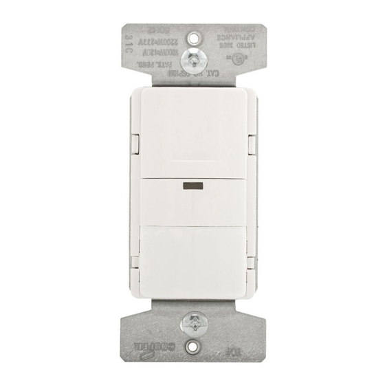
Catalog # OSP10M Occupancy Sensor (Single Output)
SPECIFICATIONS
• Single Pole and 3-Way
• 15A, 120V AC 60 Hz – Incandescent, Magnetic Low Voltage, Magnetic Ballast
10A, 120V AC, 60 Hz – LED, Compact Fluorescent, Electronic Low Voltage, Electronic Ballast
8A, 277V AC, 60 Hz – Magnetic Low Voltage, Magnetic Ballast, LED, Compact Fluorescent,
Electronic Low Voltage, Electronic Ballast
1/2 HP, 120V AC, 60 Hz – Motor
• NOTE - A Ground Connection is required in the wallbox where the sensor will be installed.
DESCRIPTION
• This Sensor Wall Switch can replace a standard wall switch in any of the following applications:
• Single location – one Single Pole switch.
• Two location – one location is the sensor and the other location is a standard 3-way switch.
• Two location – replace both 3-Way switches with sensors.
• The OSP10M can interface with an external control Switchpack.
• The OSP10M turns on automatically when a person enters the room.
• Will automatically turn OFF lights after a selectable time delay.
• The selectable time delays are 5 seconds (Test Mode), 5 minutes (factory default), 15 minutes and 30 minutes.
• Includes a light level adjustment for daylight to prevent motion from turning ON the lights.
• A green LED indicates the load status and provides a momentary flash to indicate motion.
• The OSP10M relay connections are isolated. They may be wired to a load that is powered from a different
power source than the sensor power.
SPECIAL MODES
• Reverse Mode: The reverse mode is used when the lights must stay OFF in a room while motion is detected.
If the lights are ON, a double tap of the ON/OFF button will turn off the lights and put the device into the
Reverse Mode. This allows the lights to stay OFF as long as motion is detected. After the time delay is
finished the sensor operation goes back to normal.
• Vacancy mode: This mode may be selected to prevent motion from automatically turning on the lights.
Press and hold the ON/OFF button for 5 seconds until the indicator LED blinks. Release the button while the
LED is blinking. Repeat this procedure to restore normal operation.
• Override Mode: Turns off all motion sensing and allows the device to be used as a regular ON/OFF switch
or in the unlikely event of a failure of the motion sensor. Press and hold the ON/OFF button for 10 seconds
until the indicator LED blinks for the second time (the LED will also blink at the 5 second point). Release
the button while the LED is blinking. Repeat this procedure to restore normal operation.
• Disable Manual Operation – In this mode the sensor will function normally with automatic sensing,
however the sensor will not respond to pressing the ON/OFF button. This feature is enabled by
pressing and holding the ON/OFF button for 15 seconds until the LED indicator blinks for the third time
(the LED will also blink at the 5 second and 10 second point) and then releasing the button while the
LED is blinking. Repeat this procedure to restore normal operation.
INSTALLATION INSTRUCTIONS
WARNING:
• Turn OFF circuit breaker or remove fuse(s) and verify that power is OFF before wiring.
• Never wire any electrical device with power turned ON. Wiring the device with the power on
unsafe and may cause permanent damage to the device and void the warranty.
• If you are unsure about any part of these instructions, or if the wiring does not match the
descriptions given, you should call a qualified electrician.
CAUTION:
• Must be installed and used in accordance with all applicable electrical codes.
• If a bare copper or green ground connection is not available in the wallbox, contact a quali-
electrician for installation. Do not install without proper ground connections.
• Do not exceed maximum device ratings.
• For use ONLY with permanently installed fixtures of these types:
Incandescent/Halogen, Magnetic Low Voltage (MLV), Electronic Low Voltage
(ELV), Fluorescent, Compact Fluorescent, LED.
• May also be used with motors up to 1/2 HP
• To avoid overheating and possible damage to other equipment, do not use to control receptacles.
• Use only #14 or #12 copper wire with these devices.
• Make sure the controlled load (connected to Relay OUT) is rated to handle the volt-
connected to the Relay IN wire of the OSP10M
Installing OSP10M for single pole application
Refer to wiring diagram 1A and install the sensor properly by following the
described wire connections. Once all wires are connected, using the provided
wire nuts, go to COMPLETING THE INSTALLATION.
Installing OSP10M for Switchpack control
Refer to wiring diagram 1B and install the sensor properly by following the
described wire connections. Once all wires are connected, using the provided
wire nuts, go to COMPLETING THE INSTALLATION.
Installing OSP10M for 3-way applications
NOTE that the 3-way switch is NOT wired in the traditional 3-way manner.
Refer to either wiring diagram 2A or 2B and install the sensor properly by follow-
ing the described wire connections (The sensor may be placed at either end of
3-way circuit). Once all wires are connected, using the provided wire nuts, go to
Installing OSP10M for 2 sensor applications
Refer to wiring diagram 3 and install the sensor properly by following the
described wire connections. Once all wires are connected, using the provided
wire nuts, go to COMPLETING THE INSTALLATION.
DIAGRAM 1A: SENSOR IN ONE LOCATION (NON-ISOLATED)
Hot
Black
Ground
Bare
Neutral
White
DIAGRAM 1B: SENSOR AND SWITCHPACK CONTROL
Hot Black
Green
Ground
DIAGRAM 2A: SWITCH IN LOCATION WITH HOT WIRE
First Location
Black Traveler
Hot
Black
3-Way Switch
Neutral
White
Arrow Hart
COVERAGE PATTERN
15'
8'
0
MINOR MOTION
300 SQ. FT.
MAJOR MOTION
1000 SQ. FT.
Black
120/277V
Hot
Relay IN
Relay OUT
Orange
Red
Green
3-Way
Blue
Orange Relay in
Switchpack control lines
Red Relay out
Second Location
120/277V
Hot
Black
Relay IN
Orange
Ground
Green
Bare
3-Way
Red Traveler
Neutral
White
www.eaton.com/wiringdevices
8'
15'
0
15'
36'
120/277V
Black
Light Fixture
is
Blue wire
fied
Red wire
age
120/277V
Relay OUT
Black
Red
Light
Fixture
Blue
the
www.eaton.com
EIS-0156-E (REV.A)
Advertisement
Table of Contents

Related Manuals for Eaton OSP10M


Summary of Contents for Eaton OSP10M
- Page 1 • A green LED indicates the load status and provides a momentary flash to indicate motion. • The OSP10M relay connections are isolated. They may be wired to a load that is powered from a different power source than the sensor power.
- Page 2 EATON WIRING DEVICES LIMITED 2 YEAR WARRANTY Eaton Wiring Devices (EWD) warrants this device to be free of defects in materials and workmanship in normal use and service for a period of two years from date of original purchase. THIS 2 YEAR LIMITED WARRANTY IS IN LIEU OF ALL OTHER WARRANTIES, OBLIGATIONS, OR LIABILITIES, EXPRESSED OR IMPLIED (INCLUDING ANY IMPLIED WARRANTY OF MERCHANTABILITY OR FITNESS FOR A PARTICULAR PURPOSE THAT IS IN DURATION IN EXCESS OF 2 YEARS FROM THE DATE OF ORIGINAL CONSUMER PURCHASE).
Need help?
Do you have a question about the OSP10M and is the answer not in the manual?
Questions and answers