Table of Contents
Advertisement
Quick Links
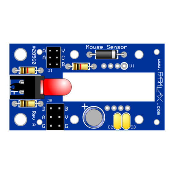
Mouse Sensor Kit (#28560)
The Parallax Mouse Sensor is a module in kit form which, when assembled, provides the tracking
functions of an optical mouse. The two-wire serial interface is directly compatible with the Parallax BASIC
®
Stamp
2 family, the Parallax Propeller, and other microcontrollers.
Features
Compact module, including illumination, optics, and custom laser-cut base
"Close-to-the-metal" register-based serial interface for maximum flexibility
Holes for mounting to other equipment
Compatible with any BS2-family BASIC Stamp
Accommodation for single or dual three-wire (servo-type) interface cables
Key Specifications
Power requirements: 5 VDC at 35 mA
Communication: Two-wire serial (clock and data)
Logic compatible with 3.3V (using external resistor) and 5V microcontrollers
Dimensions: 1.80" (45.7mm) L x 1.00" (25.4 mm) W x 0.65" (16.5 mm) H
Application Ideas
Measuring X and Y displacement on a flat surface
Detecting vibration in two dimensions over a flat surface
What Comes with the Kit
Part
Parallax No.
300-28560
U1
604-28560
LED1
350-00031
350-00032
721-28560
D1
501-00008
R1, R2
150-01021
R3
150-01022
Copyright © Parallax Inc.
Web Site: www.parallax.com
Forums: forums.parallax.com
Sales: sales@parallax.com
Technical: support@parallax.com
®
, the SX, and the Parallax Propeller
Description
Printed circuit board
MCS-12086 mouse
sensor chip
Red T1¾ LED (lens
may be red or clear)
Right-angle LED holder
Clear plastic lens/light
guide
1N5817 Schottky diode
1K 1/8 W resistor
(brown, black, red)
100Ω 1/8 W resistor
(brown, black, brown)
Mouse Sensor Kit (#28560)
Office: (916) 624-8333
Fax: (916) 624-8003
Sales: (888) 512-1024
Tech Support: (888) 997-8267
Illustration (not to scale)
v1.0 6/1/2010 Page 1 of 18
Quan.
1
1
1
1
1
1
2
1
Advertisement
Table of Contents

Subscribe to Our Youtube Channel
Related Manuals for Parallax 28560


Summary of Contents for Parallax 28560
- Page 1 Tech Support: (888) 997-8267 Mouse Sensor Kit (#28560) The Parallax Mouse Sensor is a module in kit form which, when assembled, provides the tracking functions of an optical mouse. The two-wire serial interface is directly compatible with the Parallax BASIC ®...
-
Page 2: What You Need To Provide
Wire clippers • Needle-nosed pliers • 99% isopropyl alcohol and an old (clean) toothbrush • Miniature (#0) Phillips screwdriver • Pointed tweezers • Eye protection • Copyright © Parallax Inc. Mouse Sensor Kit (#28560) v1.0 6/1/2010 Page 2 of 18... - Page 3 BASIC Stamp, Propeller, SX, etc. • Carrier board (e.g. Board of Education, Propeller Demo Board, Propeller Proto Board, etc.) • One or two servo extension cables with 3-pin headers (e.g. Parallax #805-00011) • Assembly Instructions Assemble the Circuit Board 1. The printed circuit board is marked on top with the part numbers from the “Part” column in the table above.
- Page 4 Insert the black plastic snap rivets into the corner holes, so that the heads rest in the engraved recesses: Copyright © Parallax Inc. Mouse Sensor Kit (#28560) v1.0 6/1/2010 Page 4 of 18...
- Page 5 The nuts can then be installed from the bottom, one at a time, and the screws tightened. Copyright © Parallax Inc. Mouse Sensor Kit (#28560) v1.0 6/1/2010 Page 5 of 18...
- Page 6 NOTE: Board of Education users can simply connect using two extension cables from the onboard servo headers. Make sure that servo power is jumpered to Vdd and not Vin Copyright © Parallax Inc. Mouse Sensor Kit (#28560) v1.0 6/1/2010 Page 6 of 18...
-
Page 7: Connecting And Testing
To test the Mouse Sensor further with a BASIC Stamp, wire it as shown above. Then upload the program mouse_monitor.bs2, shown at the end of this document and downloadable from the Mouse Sensor product page (search "28560" at www.parallax.com). When run, a debug window will pop up, and you should see a display that looks something like this: The program accumulates the sensor’s X and Y displacement data to show the current position. - Page 8 You will find it to be a lot more responsive with the Propeller than with the BASIC Stamp. Copyright © Parallax Inc. Mouse Sensor Kit (#28560) v1.0 6/1/2010 Page 8 of 18...
- Page 9 Propeller outputs do not rise high enough to turn off a PNP transistor powered from +5V. Therefore, an additional transistor is required to do the job. Here’s the circuit: Copyright © Parallax Inc. Mouse Sensor Kit (#28560) v1.0 6/1/2010 Page 9 of 18...
-
Page 10: Device Information
Resources and Downloads You may download free example and demo programs from the Mouse Sensor product page (search "28560" at www.parallax.com). and from the Propeller Object Exchange (obex.parallax.com). Device Information Theory of Operation The mouse sensor chip is actually a tiny camera that is continuously snapping pictures, comparing each with the one before to detect movement. - Page 11 Data writes take place by setting the data line to an output, then sending the register address as eight bits, most significant bit first, with bit 7 set to 1. Then eight data bits are clocked into the chip, most significant bit first. Copyright © Parallax Inc. Mouse Sensor Kit (#28560) v1.0 6/1/2010 Page 11 of 18...
-
Page 12: Module Specifications
It is not necessary for such a driver to have current sinking capability: a stiff pull-down is provided on the Mouse Sensor module itself. Copyright © Parallax Inc. Mouse Sensor Kit (#28560) v1.0 6/1/2010 Page 12 of 18... - Page 13 Mouse Sensor Dimensions Mouse Sensor Schematic 1N5817 Vreg SDIO /LED 0.1 F 0.1 F SCLK 47 F MCS12086 B V G 100R LED1 D A G Copyright © Parallax Inc. Mouse Sensor Kit (#28560) v1.0 6/1/2010 Page 13 of 18...
-
Page 14: Source Code
Source Code BASIC Stamp 2 Program This .bs2 program is available for download from the Mouse Sensor product page; search "28560" at www.parallax.com. ' ========================================================================= File..mouse_monitor.bs2 Purpose... Monitors data coming from Mouse Sensor (#28560). Author..Parallax E-mail..support@parallax.com Started... 24 Feb 2010 {$STAMP BS2} {$PBASIC 2.5}... - Page 15 ' DumpXYQ outputs X, Y, and Quality data to the programming port, for use with ' either DEBUG or an external program. DumpXYQ: addr = STAT GOSUB ReadAddr #IF (USE_DEBUG) #THEN IF (dat & CHNG = 0) THEN Copyright © Parallax Inc. Mouse Sensor Kit (#28560) v1.0 6/1/2010 Page 15 of 18...
- Page 16 ' ReadAddr reads a sensor chip register. Inputs: addr = address ($00 - $7F) to read. Outputs: dat = contents of the addressed register. ReadAddr: #IF (NEG_CLK) #THEN Copyright © Parallax Inc. Mouse Sensor Kit (#28560) v1.0 6/1/2010 Page 16 of 18...
- Page 17 Outputs: dat = data read from serial bus, MSB first. FOR i = 0 TO 7 dat = dat << 1 PULSOUT sclk, 25 dat.BIT0 = sdio NEXT RETURN Copyright © Parallax Inc. Mouse Sensor Kit (#28560) v1.0 6/1/2010 Page 17 of 18...
- Page 18 Propeller Application Here’s the Top Level MouseSensorMonitor.spin listing. The referenced objects are included with the archive downloadable from the Mouse Sensor page (search "28560" at www.parallax.com) or from the Propeller Object Exchange (obex.parallax.com). _clkmode = xtal1 + pll16x _xinfreq = 5_000_000...
Need help?
Do you have a question about the 28560 and is the answer not in the manual?
Questions and answers