Advertisement
Quick Links
Product Announcement:
This product is certificated to meet RoHS
Directive and Lead-Free produced definition.
Using approved critical components only is
recommended when the situation to replace
defective parts. Vender assumes no liability
express or implied, arising out of any unauthorized
modification of design or replacing non-RoHS
parts. Service providers assume all liability.
Qualified Repairability:
Proper service and repair is important to the safe,
reliable operation of all series products. The
service providers recommended by vender should
be aware of notices listed in this service manual in
order to minimize the risk of personal injury when
perform service procedures. Furthermore, the
possible existed improper repairing method may
damage equipment or products. It is recommended
that service engineers should have repairing
knowledge, experience, as well as appropriate
product training per new model before performing
the service procedures.
NOTICE:
! To avoid electrical shocks, the products should be
connected to an authorized power cord, and turn
off the master power switch each time before
removing the AC power cord.
! To prevent the product away from water or
expose in extremely high humility environment.
! To ensure the continued reliability of this
product, use only original manufacturer's
specified parts.
! To ensure following safety repairing behavior, put
the replaced part on the components side of
PWBA, not solder side.
1. Important Safety Notice
! To ensure using a proper screwdriver, follow the
! Using Lead-Free solder to well mounted the
! The fusion point of Lead-Free solder requested in
torque and force listed in assembly and
disassembly procedures to unscrew screws.
parts.
the degree of 220°C.
Advertisement

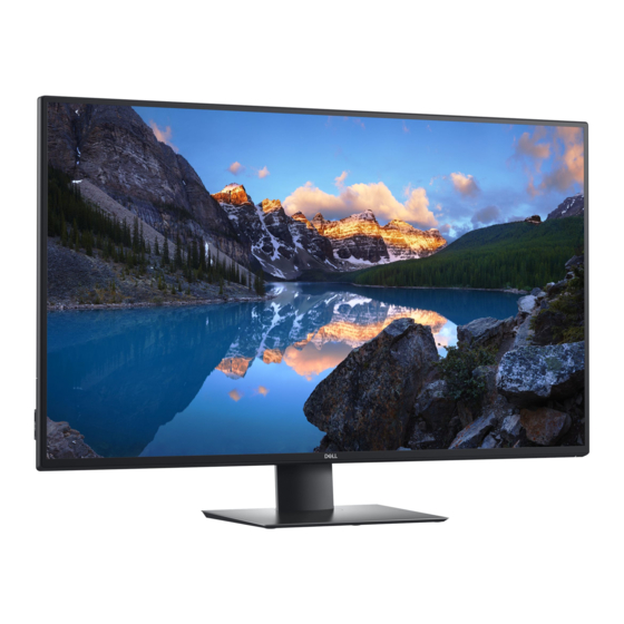
Related Manuals for Dell U4320Q


Summary of Contents for Dell U4320Q
- Page 1 1. Important Safety Notice Product Announcement: ! To ensure using a proper screwdriver, follow the This product is certificated to meet RoHS torque and force listed in assembly and Directive and Lead-Free produced definition. disassembly procedures to unscrew screws. Using approved critical components only is ! Using Lead-Free solder to well mounted the recommended when the situation to replace parts.
- Page 2 2. Exploded view diagram with list of items...
- Page 3 3. Wiring Connectivity Diagram Panel Speaker Power Board Interface Board TypeC Down USB Board USB3.0 Down3 AC In HDMI 2.0 In DP 1.4 In Function Key Board...
- Page 4 4. Disassembly and Assembly Procedures Necessary repair and test equipment: Lift the rear cover up carefully. Disconnect the USB 1. Philips-head screwdriver LVDS cable and function key cable from the 4.1 Disassembly Procedures: connectors of the interface board, and then remove Remove the monitor stand base: the rear cover.
- Page 5 4. Disassembly and Assembly Procedures Tear off acetate tape, then disconnect the panel lamp cables from the connectors of the circuit board. se a Philips-head screwdriver to remove 2pcs screws for unlocking the heat-sink. se a Philips- head screwdriver to remove 26pcs screws for unlocking the middle bezel, then remove the bezel.
- Page 6 4. Disassembly and Assembly Procedures Remove 2pcs shading tape on the left and right side Remove the circuit boards from the bracket of the panel corner, then remove 32pcs acetate chassis module carefully, and then disconnect all tapes on the specific positions of the back of panel. of the cables.
- Page 7 ±0.5 Take 1pcs interface board, connect a LVDS cable to Take 1pcs Dell nameplate, then use a locating fixture the connector of the interface board, then connect to fix the nameplate to the front bezel of the module, the power connective cable to the the interface and then move the whole unit into a laminating board.
- Page 8 4. Disassembly and Assembly Procedures Adjust the bracket chassis module, and then u se a Philips-head screwdriver to tighten 4pcs screws for locking the bracket chassis module with the panel (No.1~4 Screw size= M6x12, Torque=9 0.5kgfxcm) ± Turn over the panel module to place screen faced down.
- Page 9 4. Disassembly and Assembly Procedures Take 1pcs USB board, 1pcs conductive foam, 1pcs LVDS cable and 1pcs rear cover. Connect the LVDS cable to the connector of the USB board, then paste 1pcs conductive foam on the back of the USB board, and then locate the USB board into the correct position of the rear cover.
- Page 10 4. Disassembly and Assembly Procedures Use a Philips-head screwdriver to tighten four screws for locking mechanisms. Stick 1pcs label on the specific positions as the picture below shown. (No.1~4 screw size=M6x12; Torque=9 0.5kgfxcm) ± Take a stand base close to the monitor. Fit the two tabs on the upper part of the stand into the grooves on the back of the monitor, and then lower the stand so that the monitor mounting area snaps onto the...
- Page 11 While in self-test mode, the power LED remains white. Also, depending upon the selected input, one of the dialogs shown below will continuously scroll through the screen. Dell UltraSharp 43 Monitor No HDMI Cable The display will go into Standby Mode in 4 minutes.
-
Page 12: Built-In Diagnostics
1 Ensure that your PC is powered off. 2 Press any control button other than the power button to display the shortcut menu of Input Source. 3 Use the button to highlight USB Type-C. Dell UltraSharp 43 Monitor Input Source: Auto USB Type-C HDMI... -
Page 13: Pip/Pbp Mode
5. Trouble Shooting Instructions 4 Press and hold the button for approximately 8 seconds. 5 The USB-C Prioritization configuration message will appear. Dell UltraSharp 43 Monitor Select USB-C Prioritization: High Resolution High Data Speed U4320Q 6 Use the button to specify the preferred transfer priority. -
Page 14: Common Problems
LCD screen has • Cycle power on-off. spots • Pixel that is permanently off is a natural defect that can occur in LCD technology. • For more information on Dell Monitor Quality and Pixel Policy, see Dell Support site at: www.dell.com/support/monitors. -
Page 15: Product Specific Problems
• Cycle power On-Off. bright spots • Pixel that is permanently off is a natural defect that can occur in LCD technology. • For more information on Dell Monitor Quality and PixelPolicy, see Dell Support site at: www.dell.com/support/monitors. Brightness Picture too dim •... - Page 16 • If the Notebook requires a >65 W power adaptor, it laptop, and so on may not charge with the USB Type-C connection. • Ensure that you use only Dell approved adapter or the adapter that comes with the product. • Ensure that the USB Type-C cable is not damaged.
Need help?
Do you have a question about the U4320Q and is the answer not in the manual?
Questions and answers