Table of Contents
Advertisement
Quick Links
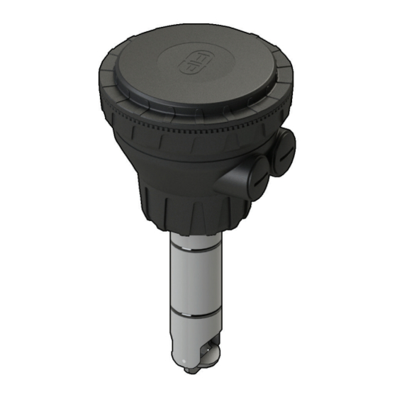
FLS F3.00.W
WIRELESS PADDLEWHEEL
FLOW SENSOR
SAFETY INSTRUCTIONS
General Statements
• Do not install and service the product without following the Instruction
Manual.
• This item is designed to be connected to other instruments which can be
hazardous if used improperly. Read and follow all associated instrument
manuals before using with it.
• Product installation and wiring connections should only be performed by
qualified staff.
• Do not modify product construction.
• To optimize the system functionality, please refer to section "System
location".
Installation and Commissioning Statements
• Remove power to the instrument before wiring input and output connections.
• Do not exceed maximum specifications using the instrument.
• To clean the unit, use only chemical compatible products.
1
Advertisement
Table of Contents

Related Manuals for FIP FLS F3.00.W

Summary of Contents for FIP FLS F3.00.W
- Page 1 FLS F3.00.W WIRELESS PADDLEWHEEL FLOW SENSOR SAFETY INSTRUCTIONS General Statements • Do not install and service the product without following the Instruction Manual. • This item is designed to be connected to other instruments which can be hazardous if used improperly. Read and follow all associated instrument manuals before using with it.
-
Page 2: Packing List
The FLS F3.00.W is a reliable solution for every kind of solid-free liquid. Easy and quick to install, it is suitable for pipes in different materials, sized from DN15 to DN600 (0.5’’ to 24’’). -
Page 3: Technical Data
It can cover also long operating distances up to 100 meters and work in presence of electromagnetic interferences generated by devices like pumps and inverters. Besides thanks to the auto-diagnostic system, the user is always informed about the lack of signal and the exhausted battery. TECHNICAL DATA General •... - Page 4 Maximum Operating Pressure / Temperature (25 years lifetime) • CPVC body: - 10 bar (145 psi) @ 25°C (77°F) - 1,5 bar (22 psi) @ 80° C (176°F) • PVDF body: - 10 bar (145 psi) @ 25°C (77°F) - 2,5 bar (36 psi) @ 100°C (212°F) •...
-
Page 5: Installation
• Optimal installation conditions: - indoor ambient - the receiver must face the transmitter. To identify the proper position please refer to the FIP mark on the box cap. Receiver must face the left side of FIP mark (see the image below) - Page 6 • To verify the correct F3.00.W system location, use the following procedures: - Insert a charged battery into the trasmitter. - To connect with FLS monitor: ▪ Follow the first calibration procedure on the monitor. ▪ Select the option wireless sensor F3.00.W. ▪...
- Page 7 Pipe Location • The six most common installation configurations shown in fig. 1 help in selecting the best location in the pipeline for paddlewheel flow sensor as well for magmeter flow sensor. • The three configurations in fig. 2 ensure that the pipe is always full: for a correct measurement the sensor can NOT be exposed to air bubbles at any time.
-
Page 8: Mounting Position
Mounting position Measuring part of sensor (rotor for paddlewheel and pins for magmeter) should be positioned at 12% of ID where, basing on insertion theory, average velocity can be measured. The reading accuracy of insertion flow sensors can be affected by: •... - Page 9 Receiver installation Wall mounting W1-W2 1. Clean the surface where the PCB must be glued 3. Remove the protective film from the PCB support already mounted 4. Install the PCB according to the picture. Installation on the upper part of the box is reccommended.
-
Page 10: General Recommendation
WIRING General recommendation Always ensure the power supply is switched off before working on the device. Make wiring connections according to wiring diagrams. • Terminals accept 26 to 12 AWG (0.08 to 2.5 mm2) • Strip around 10 mm (0.4”) of insulation from the wire tips and tin bare ends to avoid fraying. -
Page 11: Power Wiring Diagram
POWER WIRING DIAGRAM Connection to Connection to FLS M9.03, M9.07 FLS M9.02 monitor and M9.08 monitors Connection to FLS M9.03 monitor sensor input 1 Please note: on M9.02, M9.03, M9.07 and M9.08 DIR is the connection for low battery alarm. Connection to a PLC Connection for signal intensity function JUMPER IN... -
Page 12: Installation Fittings
INSTALLATION FITTINGS Type Description • Size: d20 to d50 (0.5” to 1.5”) Plastic Tees • Materials: PVC, C-PVC, PP, PVDF • Size: d63 to d225 (2” to 8”) PVC-U Clamp Saddles • Insert Materials: C-PVC, PVDF • Size: d63 to d315 316L SS Tees •... -
Page 13: K-Factor Tables
K-FACTOR TABLES K-Factor is the number of pulses which a sensor produces for one liter of measured fluid. Here below all K-Factors for water at room temperature are listed. K-Factor values can depend on the installation conditions. K-Factor has to divide the frequency generated by F3.00 in order to achieve the flow rate (l/s). - Page 14 NPT Female Threaded PVC Tee Fittings ASTM SCH. 80 PVC Tee Fittings for ASTM SCH. 80 pipes for ASTM SCH. 80 pipes (NPT threaded female ends) (female ends for solvent welding) Part No. SIZE K-Factor Part No. SIZE K-Factor TFNV20B 0.50"...
- Page 15 Installation on C-PVC pipes ISO Metric CPVC Tee Fitings for ISO SDR 21 ISO Clamp Saddles for ISO SDR 21 pipes pipes (female ends for solvent welding) Part No. K-Factor Part No. K-Factor TFIC20B 235,45 SVIC063BVC 21,69 TFIC25B 142,46 SVIC075BVC 14,98 SVIC090BVC 9,88...
- Page 16 NPT Female Threaded PP Tee Fittings for ASTM SCH.80 pipes ISO Clamp Saddles for ISO SDR 21 pipes (NPT threaded female ends) Part No. K-Factor Part No. K-Factor TFNM20B 0.50" 1/2" 212,17 SVIC063BME 27,50 TFNM25B 0.75" 3/4" 135,32 SVIC075BME 18,56 TFNM32B 1.00"...
- Page 17 Installation on PVDF pipes ISO Metric PVDF Tee Fittings for ISO SDR 33 ISO Clamp Saddles for ISO SDR 33 pipes pipes (female ends for socket welding) Part No. K-Factor Part No. K-Factor TFIF20B 225,06 SVIF063BF 20,58 TFIF25B 139,38 SVIF 075BF 14,09 SVIF 090BF 9,29...
- Page 18 Installation on Metal pipes 316L SS Threaded Tees (BSP Female Threads) Part No. K-Factor TFFX20 1/2" TFFX25 157,06 TFFX32 1" 92,84 TFFX40 1" 1/4 51,52 Metal Strap-on Saddles Metal Strap-on Saddles mounted on Cast Iron pipes mounted on Other Metal pipes Part No.
-
Page 19: Ordering Data
Correction formula for K-Factor calculation according to real internal diameter: K-Factor_NEW = (K-Factor x ID²) / ID_NEW² ID = Value in the table for the internal diameter (in mm) ID_NEW = New value for the real internal diameter (always in mm) K-Factor = Value in the table K-Factor_NEW = New K-Factor value for the specified internal diameter Example:... - Page 20 FIP - Formatura Iniezione Polimeri S.p.A. Loc. Pian di Parata 16015 Casella Genova - Italy Tel. +39 010 96211 Fax +39 010 9621209 www.flsnet.it...
Need help?
Do you have a question about the FLS F3.00.W and is the answer not in the manual?
Questions and answers