Table of Contents
Advertisement
Available languages
Available languages
Quick Links
Exclusive distributor in the Kingdom
SAmnAn foR TRAdE And mAinTEnAncE
P.o. BoX 4784, TARig Bin ZiAd STREET
RiyAdh 11412, Kingdom of SAudi ARABiA
Ph: 447-7777 fAX: 447-5555
uSA
293 WRighT STREET, dELAVAn, Wi 53115 WWW.STA-RiTE.com
Ph: 262-728-5551
© 2013 Pentair, Ltd. All Rights Reserved.
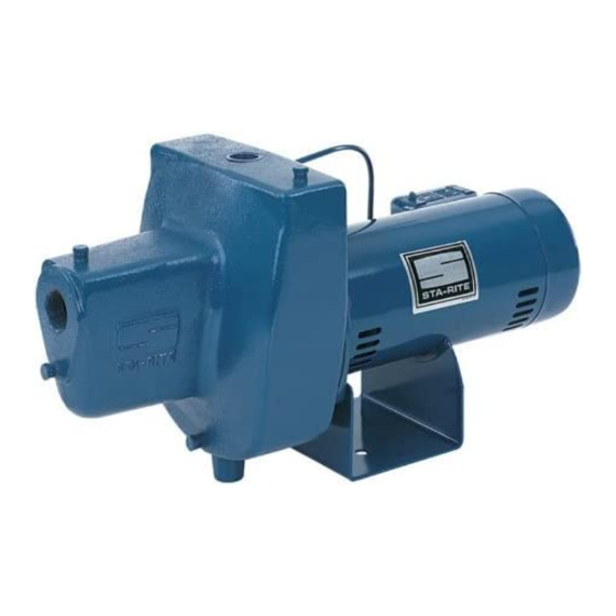
HN and SN Series
for best possible performance and continuous, satisfactory
operation, read these instructions before installing your new pump.
Should service be required, this manual can be a valuable guide.
it should be kept near the installation for ready reference.
Record nameplate data from pump on blank nameplate inside this
manual for future reference.
Shallow Well Jet Pumps
Important
OWNER'S MANUAL
2400 0496
SX960 (Rev. 03/21/13)
Advertisement
Table of Contents

Subscribe to Our Youtube Channel
Related Manuals for Pentair STA-RITE HN Series


Summary of Contents for Pentair STA-RITE HN Series
- Page 1 SAmnAn foR TRAdE And mAinTEnAncE P.o. BoX 4784, TARig Bin ZiAd STREET RiyAdh 11412, Kingdom of SAudi ARABiA Ph: 447-7777 fAX: 447-5555 293 WRighT STREET, dELAVAn, Wi 53115 WWW.STA-RiTE.com Ph: 262-728-5551 SX960 (Rev. 03/21/13) © 2013 Pentair, Ltd. All Rights Reserved.
- Page 2 Safety Important Safety Instructions General Safety Risk of explosion. The pump body may SAVE THESE INSTRUCTIONS - This manual contains explode if used to boost pressure above the pressures important instructions that should be followed during shown in Specifications. Do not use this pump with inlet installation, operation, and maintenance of the product.
-
Page 3: Warranty
Warranty Limited Warranty STA-RITE warrants to the original consumer purchaser (“Purchaser” or “You”) of the products listed below, that they will be free ® from defects in material and workmanship for the Warranty Period shown below. Product Warranty Period whichever occurs first: Water Systems Products — jet pumps, small centrifugal pumps, 12 months from date of original installation, submersible pumps and related accessories or 18 months from date of manufacture Pro-Source™... -
Page 4: Specifications • Installation
Specifications • Installation Table I – Specifications Maximum Maximum Minimum Head, Maximum Head, Maximum Head, Maximum Flow, Maximum Flow, Model Working Working Meters Meters Feet GPM@Ft. Head LPM@M Head Pressure, PSI Pressure, BAR HND-SA 21@70 79@21 HNE-SA 28@70 106@21 HNF-SA 1-1/2 SNC-SA 9@70... -
Page 5: Installation
Installation Cased Well Installation, Installation for Surface Water 2” or Larger Casing 1. The pump should be installed as close to the water as possible, with the fewest possible fittings 1. Mount the pump as close to the well as possible. (especially elbows) in the suction pipe. The suction 2. - Page 6 Discharge Pipe and Tank Connections Pre-Charge Tank Connection Standard Tank Connection 1. Install two tees in the pump discharge port (see 1. Install one tee in the pump discharge port Figure 4). The pipe size must be at least as large as (see Figure 5). the discharge port. Pump priming To household tee and plug water system To household water system...
- Page 7 Installation Pressure Booster System Installation Pressure gauge To household Risk of explosion. Install a relief valve as water system Union and gate valve for shown capable of passing entire pump flow at 75 PSI. service access Low pressure Pump body may explode if internal pressure exceeds cutoff switch 75 PSI.
- Page 8 Electrical Risk of electrical shock. Can shock, burn or kill. Disconnect power before working on pump, motor, pressure switch, or wiring. Never apply 220 volts to a motor set for LOW (115/127). Motor Switch Settings NOTICE Single phase motors are dual voltage and are factory set to HIGH volt setting. Motor terminal board (located under the motor end cover) should look like that shown in Figure 8. Use the instructions to set your single phase motor to match power source.
-
Page 9: Electrical Operation
Electrical • Operation Wiring Risk of fire. Incorrect voltage can cause a fire or seriously damage the motor and voids the warranty. The supply voltage must be within ±10% of the motor nameplate voltage. NOTICE Dual-voltage motors are factory wired for HIGH Fill pump and piping through priming tee (220/230) volts. -
Page 10: Troubleshooting
Troubleshooting Symptom Possible Cause(s) Corrective Action Disconnect switch is off. Be sure switch is on. Fuse is blown or circuit breaker tripped. Replace fuse or reset circuit breaker. Starting switch is defective. DISCONNECT POWER; Replace starting switch. Refer to Electrical. DISCONNECT POWER; check and tighten all wiring. Motor will not run. Risk of electric shock. Can shock, burn or kill. Capacitor Wires at motor are loose, disconnected, or wired voltage may be hazardous. -
Page 11: Repair Parts
Repair Parts HN Series Nozzle Cleanout Port Ref. Part Description Qty. HND-SA 3/4 HP HNE-SA 1 HP HNF-SA 1-1/2 HP 2763 0197 Motor A100DLL A100ELL A100FLL Capscrew 3/8-16x1-1/4” Lg. U30-75ZP – Hex Hd. Capscrew 3/8-16x1-1/2” Lg. – U30-76ZP Hex Hd. Water Slinger 17351-0009 Seal Plate Assembly N3-1043P L3-10 Gasket, Seal Plate... - Page 12 Repair Parts SN Series 2352 0396 Ref. Part Description Qty. SNC-SA 1/2 HP SND-SA 3/4 HP Motor A100CLL A100DLL #§2 Water Slinger 17351-0009 Seal Plate N3-9 #§4 Seal Plate Gasket N20-35 #§5 Shaft Seal U109-6A Impeller J105-40P J105-42P Diffuser L1-25P #§8 Diffuser Gasket N20-34 Quick Connect - 1/4” NPT U11-217P...
- Page 13 إصالح األجزا ء SN سلسلة 4/3 حصانSND-SA 2/1 حصانSNC-SA الكمية وصف الجزء المرجع 2352 0396 A100DLL A100CLL الموتور 17351-0009 حلقة حجز المياه 2§# N3-9 لوح مانع التسرب N20-35 حشية لوح منع التسرب 4§# U109-6A مانع تسرب العمود 5§# J105-42P J105-40P الدفاعة L1-25P رشاشة...
- Page 14 إصالح األجزا ء HN سلسلة Nozzle منفذ تنظيف Cleanout الفوهة Port 2/1-1 حصانHNF-SA 1 حصانHNE-SA 4/3 حصانHND-SA الكمية وصف الجزء المرجع 2763 0197 A100FLL A100ELL A100DLL الموتور .برغي برأس 61-8/3×4/1-1 بوصة – U30-75ZP .رأس سدادس .برغي برأس 61-8/3×2/1-1 بوصة U30-76ZP – .رأس...
- Page 15 استكشاف األعطال وإصالحه ا اإلجراء التصحيحي األسباب المحتملة ال ع َرض .تأكد من تشغيل المفتاح .مفتاح الفصل غير مشغل .استبدل المنصهر أو أعد ضبط قاطع الدائرة .المنصهر محترق أو قاطع الدائرة مشغل .افصل الطاقة، استبدل مفتاح التشغيل .مفتاح التشغيل معيب الموتور ال يعمل .راجع...
- Page 16 الكهرباء • التشغي ل التوصيالت السلكية خطر الحريق. قد تؤدي الفولتية الخاطئة إلى نشوب حريق أو ±10% تلف جسيم بالمحرك وإبطال الضمان. يجب أن يكون جهد اإلمداد ضمن .من الجهد المكتوب على بطاقة بيانات الموتور مالحظة المواتير مزدوجة الفولتية مزودة في المصنع بتوصيالت سلكية امأل...
- Page 17 كهربائ ي خطر الصدمة الكهربائية. إمكانية حدوث صدمة أو حرق أو الوفاة. افصل الطاقة قبل العمل في المضخة أو المحرك أو مفتاح الضغط أو التوصيالت .(127/115( السلكية. تجنب مطل ق ً ا استخدم تيار 022 فولت مع موتور مضبوط على فولتية منخفضة إعدادات...
- Page 18 التركي ب تركيب نظام معزز الضغط مقياس الضغط إلى نظام المياه خطر االنفجار. قم بتركيب صمام تصريف كما الموضح يمكنه المنزلي وصلة وصمام بوابي لوصول تمرير تدفق المضخة الكامل عند ضغط 57 رطل في البوصة المربعة. قد ينفجر الخدمة مفتاح إيقاف تشغيل .جسم...
- Page 19 قم بتفريغ وصالت األنابيب والخزا ن وصلة خزان قياسية وصلة خزان الشحن المسبق ) واحدة في منفذ تفريغ المضخةT( 1. قم بتركيب وصلة تي .(4 ) في منفذ تفريغ المضخة (انظر الشكلT( 1. قم بتركيب وصلتي تي .(5 (انظر الشكل .يجب...
- Page 20 التركي ب التركيب مع المياه السطحية ،تركيب البئر المغلف غالف 2 بوصة أو أكبر 1. ينبغي تركيب المضخة بالقرب من المياه بقدر اإلمكان، باستخدام أقل تركيبات ممكنة (وبخاصة األكواع) في أنبوب السحب. وينبغي أن يكون .1. قم بتركيب المضخة بالقرب من البئر بقدر اإلمكان .أنبوب...
- Page 21 المواصفات • التركي ب الجدول 1 – المواصفات ،الحد األقصى للتدفق الطقاة ،الحد األقصى للتدفق الحد األقصى لضغط جالون في الدقيقة الحد األقصى لضغط الحد األقصى الحد األقصى الحد األدنى الكهربية القوة لتر في الدقيقة عند العمل، بالرطل في الطراز عند قياس االرتفاع العمل، بالبار لالرتفاع، بالقدم لالرتفاع، باألمتار لالرتفاع، باألمتار...
- Page 22 الضما ن الضمان المحدود . للمشتري المستهلك األصلي ("المشتري" أو "أنت") للمنتجات المدرجة أدناه خلوها من العيوب في المواد والصنعة لمدة الضمان الموضحة أدناهSTA-RITE تضمن مدة الضمان المنتج : ً أيهما يأتي أو ال منتجات أنظمة المياه — المضخات النافورية ومضخات الضغط المركزي الصغيرة والمضخات القابلة ،21 شه...
- Page 23 السالم ة إرشادات هامة للسالمة السالمة العامة خطر انفجار. قد ينفجر جسم المضخة في حالة استخدامها احتفظ بهذه اإلرشادات - يحتوي هذا الدليل على إرشادات هامة يتعين اتباعها لدفع ضغط أكبر من الضغوط الموضحة في المواصفات . ال تستخدم هذه . ً أثناء تركيب المنتج وتشغيله وصيانته. احتفظ بهذا الدليل للرجوع إليه مستقب ال المضخة...
- Page 24 . ً سج ِّ ل بيانات لوحة البيانات من المضخة على لوحة البيانات الفارغة داخل هذا الدليل للرجوع إليها مستقب ال 293 WRighT STREET, dELAVAn, Wi 53115 :الهاتف 262-728-5551 :الفاكس 262-728-4461 :موقع الويب sta-rite.com SX960 (Rev. 03/21/13) © 2013 Pentair, Ltd. All Rights Reserved...
Need help?
Do you have a question about the STA-RITE HN Series and is the answer not in the manual?
Questions and answers