Table of Contents
Advertisement
Quick Links
Advertisement
Table of Contents

Related Manuals for TECH ST-707


Summary of Contents for TECH ST-707
- Page 2 Declaration of Conformity No. 32/2010 Hereby, we declare under sole responsibility that the ST-707 230V 50Hz thermoregulator manufactured TECH, headquartered in Wieprz 1047A, 34-122 Wieprz, is compliant with the Regulation by the Ministry of Economy. (Journal of Laws Dz.U. 155 Item 1089) of July 21, 2007 implementing provisions of the Low Voltage Directive (LVD) 2006/95/EC of January 16, 2007.
- Page 3 ATTENTION! High voltage! Make sure the regulator is disconnected from the mains before working on the power supply (cable connections, device installation, etc.)! All connection works must only be carried out by qualified electricians. Before activating the controller, measure the motor resetting efficiency and inspect wire insulation.
-
Page 5: Description
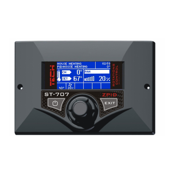
I. Description Temperature regulator ST–707 is designed for CH boilers equipped with a wormwheel feeder. It controls the water circulation pump , the hot usable water pump (HUW), the floor heating pump, the circulation pump, the blow-in (fan) and the fuel feeder. This device may also cooperate with two three-way or four-way valves, the room regulator ST-208, the GSM module and the Ethernet module. - Page 6 Each controller should be set individually, for own needs, depending on the type of fuel used for burning as well as the type of the boiler. The TECH company will not be liable for any incorrect settings of the controller.
-
Page 7: Functions Of The Regulator
Each controller should be set individually for personal needs, depending on the type of fuel used for burning as well as the type of the boiler. The TECH company shall not be liable for any incorrect settings of the controller. -
Page 8: Ii.2. Homepage
regulator, in which the blow-in and fuel feeding proceeds automatically according to the PID algorithm, oscillating around the temperature set by the user. If the temperature unexpectedly rises by more than 5 C above the set value, the so-called supervision mode will be activated. Supervision mode –... -
Page 9: Ii.4. Ignition
thermoregulator operation screens. They are: CH screen (the current boiler operation mode is displayed), ➢ valve 1 (displays the operational parameters of the first valve), ➢ valve 2 (displays the operational parameters of the second valve). ➢ manufacturer's screen - this view is unavailable to the user. This is ➢... -
Page 10: Ii.7. Manual Mode
II.7. Manual mode For the user's convenience, the regulator has been equipped with a Manual operation module. In this function, each executive device (the feeder, the blow-in, the CH pump, the HUW pump, the circulation pump and the floor pump) is activated and deactivated independently of the others. -
Page 11: Ii.8.B) Reboiler Priority
II.8.b) Reboiler priority In this mode, the reboiler pump (HUW) is turned on first, until the set temperature is reached. After reaching the set reboiler temperature, the HUW pump shuts down and causes activation of the CH pump. The CH pump operates constantly, until the moment when the temperature at the reboiler drops below the set value. -
Page 12: Ii.9. Weekly Control
the set activation threshold (see the pump activation temperature function) and operates until the set temperature is reached. The pump will be activated again when the temperature drops below the set value and the set hysteresis. In the summer mode, one sets only the set temperature in the boiler which additionally heats the water in the reboiler (the set boiler temperature is at the same time the set reboiler temperature). -
Page 13: Ii.10. Fuel Granulation
Example Monday - Friday preset: 3 , temp. -10 C (temperature change – 10 preset: 4 , temp. -10 C (temperature change – 10 preset: 5 , temp. -10 C (temperature change – 10 Saturday - Sunday preset: 16 , temp. 5 C (temperature change +5 preset: 17 , temp. -
Page 14: Ii.12.C) Room Regulator
After activation of the TECH Regulator options on the main screen of the controller at the top part of the display, the letter "P" will appear. Flashing letter "P"... -
Page 15: Switch On
expectation, is should be registered by entering the module number (this is number of the valve in accordance with the documentation) and then several parameters should be set. Switch on This feature allows you to temporarily make the valve inactive. 2. -
Page 16: Minimum Opening
5. Minimum opening In this function, the minimum value of the valve opening is set. Below this value, the mixing valve will not close any further. 6. Valve type With the use of this option, the user selects the type of the valve: CH or floor. - Page 17 must be determined for external temperatures of - 20ºC, 0ºC and 20ºC. The more points constructing the curve, the greater its accuracy, which allows its flexible shaping. In our case three points, seem a very good compromise between the accuracy and the ease in setting the course of this curve.
-
Page 18: Return Protection
12. Room temperature difference This function is active only when the unit is operated with a (standard or TECH) room thermostat. When the room thermostat reaches the desired temperature in the house/flat (reports heated up condition), the valve will close to such an extent so that the temperature downstream of the valve drops by the <room... -
Page 19: Ii.12.E) Gsm Module
NOTE: If the installation includes a TECH room thermostat with RS communication (four-wire cable), you may choose an option providing dynamic control for the mixing valve 13. Factory settings This parameter allows you to restore the mixing valve settings saved by the manufacturer. - Page 20 If ST-707 controller is equipped with an additional GSM module, in order to activate this device, it is required to start the activated option (MENU> Installer menu>...
-
Page 21: Ii.12.H) Huw Hysteresis
II.12.h) HUW hysteresis This option is used to set the hysteresis of the set temperature in the reboiler. This is the maximum difference between the set temperature (that is the one required in the reboiler) and the current temperature in the reboiler, at which the HUW pump will b activated (for example: when the set temperature has the value of 55 C and the hysteresis is 5... -
Page 22: Ii.11.A) Pid Selection
mode will be replaced with a standard support mode and it will be activated when the set temperature is exceeded. II.11.a) PID selection After turning off the PID regulation function, the controller will operate as an ordinary two-state controller and the following additional functions will appear in the main menu: feeding time ➢... -
Page 23: Ii.11.B) Language Selection
Enter a four digit code to access the controller's servicing functions. Such a code is in possession of the manufacturer of the boiler as well as the TECH company. II.13. Factory settings The regulator is pre-configured for operation. However, it should be adjusted for own needs. -
Page 24: Ii.14. About The Program
II.14. About the program The boiler manufacturer's logo along with the version of the regulator software will appear upon activation of this option on the display. III. Protections To ensure maximum safe and unfailing operation, the regulator has been equipped with a number of protections. In the event of an alarm, a sound signal is activated and a relevant message is shown on the display. -
Page 25: Iii.4. Anti-Boiling Protection For The Water In The Boiler
active until the sensor is replaced with a new one. If the HUW sensor is damaged, press the Menu button, which will turn off the alarm and the controller will return to the single pump (CH) operation mode. To allow the boiler to work in all modes, the sensor must be replaced with a new one. -
Page 26: Iii.8. Fuse
IV. Maintenance The Technical condition of conduits in the ST-707 zPID controller should be checked before the heating season and in the course of it. One should also check fastening of the controller, clean it from dust and other dirt. -
Page 27: Installation
- cable feeding the floor pump ended with a plug L = 2.5m – 1pc. - sensor of HUW pump ended with a plug, TECH type L = 2.5m – 1pc. - sensor of floor pump ended with a plug, TECH type L = 2.5m – 1pc. -
Page 29: Table Of Contents
I. Description.................. 5 II. Functions of the regulator............7 II.1. Basic definitions..............7 II.2. Homepage................8 II.3. Screen view................8 II.4. Ignition................9 II.5. Set CH................. 9 II.6. Set HUW................9 II.7. Manual mode..............10 II.8. Operation mode..............10 II.8.a) House heating...............10 II.8.b) Reboiler priority............11 II.8.c) Parallel pumps...............11 II.8.d)Summer mode..............11 II.9. - Page 30 III. Protections................24 III.1. Temperature alarm..............24 III.2. Thermal protection..............24 III.3. Automatic sensor control............24 III.4. Anti-boiling protection for the water in the boiler.....25 III.5. Temperature protection............25 III.6. Protection of fuel container...........25 III.7. Fuel container protection............25 III.8. Fuse.................. 26 IV. Maintenance................26 V.
- Page 31 We are committed to protecting the environment. Manufacturing electronic devices imposes an obligation of providing for environmentally safe disposal of used electronic components and devices. Hence, we have been entered into a register kept by the Inspection For Environmental Protection. The crossed-out bin symbol on a product means that the product may not be disposed of to household waste containers.
- Page 32 - 32 -...
Need help?
Do you have a question about the ST-707 and is the answer not in the manual?
Questions and answers