
Related Manuals for ASROCK UTX-115


Summary of Contents for ASROCK UTX-115
- Page 1 UTX-115 User Manual Version 1.0 Published March 2021 Copyright©2021 ASRockInd INC. All rights reserved.
- Page 2 Copyright Notice: No part of this documentation may be reproduced, transcribed, transmitted, or translated in any language, in any form or by any means, except duplication of documentation by the purchaser for backup purpose, without written consent of ASRockInd Inc. Products and corporate names appearing in this documentation may or may not be registered trademarks or copyrights of their respective companies, and are used only for identification or explanation and to the owners’...
-
Page 3: Table Of Contents
Contents 1 Introduction ............5 1.1 Package Contents ............5 1.2 Specifications ..............6 1.3 Motherboard Layout ............8 1.4 I/O Panel ................ 10 2 Installation ............11 2.1 Screw Holes ..............11 2.2 Pre-installation Precautions ........... 11 2.3 Installation of Memory Modules (SO-DIMM) ....12 2.4 Expansion Slots ............. - Page 4 4 Software Support ..........33 4.1 Install Operating System ..........33 4.2 Support CD Information ..........33 4.2.1 Running Support CD ..........33 4.2.2 Drivers Menu ............33 4.2.3 Utilities Menu............33 4.2.4 Contact Information ..........33...
-
Page 5: Introduction
Chapter 1: Introduction Thank you for purchasing ASRockInd UTX-115 motherboard, a reliable motherboard produced under ASRockInd’s consistently stringent quality control. It delivers ex- cellent performance with robust design conforming to ASRockInd’s commitment to quality and endurance. In this manual, chapter 1 and 2 contain introduction of the motherboard and step- by-step guide to the hardware installation. -
Page 6: Specifications
1.2 Specifications Form Dimensions 111.76 x 116.84 mm (10 layer) Factor ® Intel Apollo Lake SoC Processor - UTX-115D (N4200, QC, 1.10GHz, 6W) Processor - UTX-115J (J3455, QC, 1.50GHz, 10W) System - UTX-115L (N3350, DC, 1.10GHz, 6W) Chipset 1 x M.2 (KEY E, 2230) with PCIe x1 and USB2.0 for Wireless Expansion 1 x M.2 (KEY B, 3042/3052) with USB 2.0+... - Page 7 LVDS/ Inverter Internal Serial 1 x COM (RS-232/422/485) Connector Parallel 1 x LPC Header eMMC 32G/64G Watchdog Output From Super I/O to drag RESETCON# Timer Interval 256 segments, 0,1,2…255sec Input PWR +12V DC-In AT/ATX Supported Power AT: Directly PWR on as power input ready Requirements Power On ATX: Press button to PWR on after power...
-
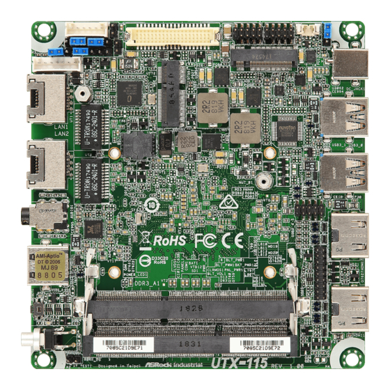
Page 8: Motherboard Layout
1.3 Motherboard Layout 1 2 3 4 BLT_PWR1 PWR_JP1 PANEL1 COM1 BLT_PWM1 BKT_PWR1 CLRMOS1 M.2 KEY B PNL_PWR1 DC_JACK1 BLT_VOL1 LAN1 USB3_0 LAN2 USB3_1 USB2_4_5 AUDIO1 HDMI2 LPC1 USB2_2 HDMI1 DDR3_A1 (Support DDR3L Only) RESET1 PWRBTN1 DDR3_B1 (Support DDR3L Only) UTX-115 Industrial... - Page 9 1 : Inverter Power Control Wafer (BLT_PWR1) 2 : Backlight Power Select (LCD_BLT_VCC) (BKT_PWR1) 3 : BL1, BL2 4 : Panel Power Select (LCD_VCC) (PNL_PWR1) 5 : LVDS Panel Connector 6 : System Panel Header 7 : COM Port Heder 8 : Battery Connector (BAT1) 9 : ATX/AT Mode Select (PWR_JP1) 10 : USB2.0 Connector (USB2_4_5)
-
Page 10: I/O Panel
1.4 I/O Panel LAN RJ-45 Port (LAN1) USB 2.0 Port (USB2_2) LAN RJ-45 Port (LAN2) Reset Button 3.5mm Audio Jack (CTIA Standard) Power Button HDMI Port (HDMI1) USB 3.1 Port (USB3_0) HDMI Port (HDMI2) DC Jack Port (+12V Only) USB 3.1 Port (USB3_1) -
Page 11: Installation
Chapter 2: Installation This is a 111.76 x 116.84 mm form factor motherboard. Before you install the moth- erboard, study the configuration of your chassis to ensure that the motherboard fits into it. Make sure to unplug the power cord before installing or removing the motherboard. -
Page 12: Installation Of Memory Modules (So-Dimm)
2.3 Installation of Memory Modules (SO-DIMM) UTX-115 provides two 204-pin DDR3 (Double Data Rate 3) SO-DIMM slots, which supports dual channel DDR3L SDRAM only. Step 1. Align a SO-DIMM on the slot such that the notch on the SO-DIMM matches the break on the slot. -
Page 13: Expansion Slots
2.4 Expansion Slots (M.2 and SIM Sockets) There are 2 M.2 sockets and 1 SIM socket on this motherboard. SIM Socket: 1 x SIM socket connected to M.2 Key B. M.2 Sockets: 1 x M.2 (KEY E, 2230) socket supports PCIe x1 and USB2.0 for Wire- less. -
Page 14: Jumpers Setup
2.5 Jumpers Setup The illustration shows how jumpers are setup. When the jumper cap is placed on pins, the jumper is “Short”. If no jumper cap is placed on pins, the jumper is “Open”. The illustration shows a 3-pin jumper whose pin1 and pin2 are “Short”... - Page 15 Backlight Control Level 1-2: From eDP PWM to CON_LBKLT_CTL 2-3: From LVDS PWM to CON_LBKLT_CTL (3-pin BLT_PWM1) (see p.8 No. 14) BL1, BL2 Open : Protect LCD_BLT_VCC (2-pin BL1) Short : No Protect LCD_BLT_VCC (see p.8 No. 3) Open : Protect R_LVDD (2-pin BL2) Short : No Protect R_LVDD (see p.8 No.
-
Page 16: Onboard Headers And Connectors
2.6 Onboard Headers and Connectors Onboard headers and connectors are NOT jumpers. Do NOT place jumper caps over these headers and connectors. Placing jumper caps over the headers and connectors will cause permanent damage of the motherboard! COM Port Header (9-pin COM1) (see p.8 No. - Page 17 System Panel Header This header accommodates several system front panel (9-pin PANEL1) functions. (see p.8, No. 6) Connect the power switch, reset switch and system status indicator on the chassis to this header according to the pin assignments below. Note the positive and negative pins before connecting the cables.
- Page 18 USB 2.0 Header There is one header on this motherboard. (9-pin USB2_4_5) (see p.8, No. 10) Battery Connector Connect the battery to this connector. (2-pin BAT1) +VBAT GND (see p.8, No. 8)
-
Page 19: Uefi Setup Utility
Chapter 3: UEFI SETUP UTILITY 3.1 Introduction This section explains how to use the UEFI SETUP UTILITY to configure your system. The UEFI chip on the motherboard stores the UEFI SETUP UTILITY. You may run the UEFI SETUP UTILITY when you start up the computer. Please press <F2>... -
Page 20: Navigation Keys
3.1.2 Navigation Keys Please check the following table for the function description of each navigation key. Navigation Key(s) Function Description Moves cursor left or right to select Screens Moves cursor up or down to select items + / - To change option for the selected items <Enter>... -
Page 21: Advanced Screen
3.3 Advanced Screen In this section, you may set the configurations for the following items: CPU Configu- ration, Chipset Configuration, Storage Configuration, Super IO Configuration, ACPI Configuration and Trusted Computing. Setting wrong values in this section may cause the system to malfunction. Instant Flash Instant Flash is a UEFI flash utility embedded in Flash ROM. -
Page 22: Cpu Configuration
3.3.1 CPU Configuration Intel SpeedStep Technology Intel SpeedStep technology is Intel’s new power saving technology. Pro- cessors can switch between multiple frequencies and voltage points to en- able power saving. The default value is [Enabled]. Configuration options: ® [Enabled] and [Disabled]. If you install Windows OS and want to enable this function, please set this item to [Enabled]. -
Page 23: Chipset Configuration
3.3.2 Chipset Configuration DRAM Frequency If [Auto] is selected, the motherboard will detect the memory module(s) inserted and assign the appropriate frequency automatically. Share Memory Configure the size of memory that is allocated to the integrated graphics processor when the system boots up. Active LVDS Use this to enable or disable the LVDS. -
Page 24: Storage Configuration
3.3.3 Storage Configuration SATA Controller(s) Use this item to enable or disable the SATA Controller feature. SATA Mode Selection Use this to select SATA mode. Configuration options: [IDE Mode] and [AHCI Mode]. The default value is [AHCI Mode]. AHCI (Advanced Host Controller Interface) supports NCQ and other new features that will improve SATA disk perfor- mance but IDE mode does not have these advantages. -
Page 25: Super Io Configuration
3.3.4 Super IO Configuration Serial Port 1 Configuration Serial Port Use this to set parameters of COM1. Type Select Use this to select COM1 port type. WDT Timeout Reset This allows users to enable/disable the Watch Dog Timer timeout to reset system. -
Page 26: Acpi Configuration
3.3.5 ACPI Configuration Suspend to RAM Use this item to select whether to auto-detect or disable the Suspend-to- RAM feature. Select [Auto] will enable this feature if the OS supports it. ACPI HPET Table Use this item to enable or disable ACPI HPET Table. The default value is [Enabled]. -
Page 27: Trusted Computing
3.3.6 Trusted Computing Security Device Support Enable or disable BIOS support for security device. -
Page 28: Hardware Health Event Monitoring Screen
3.4 Hardware Health Event Monitoring Screen In this section, it allows you to monitor the status of the hardware on your system, including the parameters of the CPU temperature, motherboard temperature, CPU fan speed, chassis fan speed, and the critical voltage. FAN1 Setting This allows you to set fan 1’s speed. -
Page 29: Security Screen
3.5 Security Screen In this section, you may set, change or clear the supervisor/user password for the system. Supervisor Password Set or change the password for the administrator account. Only the ad- ministrator has authority to change the settings in the UEFI Setup Utility. Leave it blank and press enter to remove the password. -
Page 30: Boot Screen
3.6 Boot Screen In this section, it will display the available devices on your system for you to config- ure the boot settings and the boot priority. Boot From Onboard LAN Use this item to enable or disable the Boot From Onboard LAN feature. Setup Prompt Timeout This shows the number of seconds to wait for setup activation key. - Page 31 CSM (Compatibility Support Module) Enable to launch the Compatibility Support Module. Please do not disable unless you’re running a WHCK test. If you are using Windows 8.1 64-bit and all of your devices support UEFI, you may also disable CSM for faster boot speed.
-
Page 32: Exit Screen
3.7 Exit Screen Save Changes and Exit When you select this option, it will pop-out the following message, “Save configuration changes and exit setup?” Select [OK] to save the changes and exit the UEFI SETUP UTILITY. Discard Changes and Exit When you select this option, it will pop-out the following message, “Discard changes and exit setup?”... - Page 33 Chapter 4: Software Support 4.1 Install Operating System ® ® This motherboard supports Microsoft Windows operating systems: 10 64-bit. Be- cause motherboard settings and hardware options vary, use the setup procedures in this chapter for general reference only. Refer to your OS documentation for more information.
Need help?
Do you have a question about the UTX-115 and is the answer not in the manual?
Questions and answers