ASROCK A55iCafe User Manual
Asrock
Hide thumbs
Also See for A55iCafe:
- User manual (115 pages) ,
- Manual (95 pages) ,
- Installation manual (27 pages)

Related Manuals for ASROCK A55iCafe


Summary of Contents for ASROCK A55iCafe
-
Page 1: User Manual
A55iCafe User Manual Version 1.0 Published August 2011 Copyright©2011 ASRock INC. All rights reserved. -
Page 2: Copyright Notice
ASRock. ASRock assumes no responsibility for any errors or omissions that may appear in this manual. With respect to the contents of this manual, ASRock does not provide warranty of any kind, either expressed or implied, including but not limited to the implied warran- ties or conditions of merchantability or fitness for a particular purpose. -
Page 3: Table Of Contents
Expansion Slots (PCI and PCI Express Slots) ......17 Dual Graphics Operation Guide ..........18 Dual Monitor and Surround Display Features ......20 ASRock Smart Remote Installation Guide ......... 23 Jumpers Setup ................24 Onboard Headers and Connectors ........25 2.10 Serial ATA (SATA) / Serial ATA2 (SATA2) Hard Disks... - Page 4 3. UEFI SETUP UTILITY............37 Introduction ................37 3.1.1 UEFI Menu Bar ..............37 3.1.2 Navigation Keys ............... 38 Main Screen ................38 OC Tweaker Screen..............39 Advanced Screen ..............43 3.4.1 CPU Configuration ............44 3.4.2 North Bridge Configuration ..........45 3.4.3 South Bridge Configuration ..........
-
Page 5: Introduction
In case any modifications of this manual occur, the updated ver- sion will be available on ASRock website without further notice. You may find the latest VGA cards and CPU support lists on ASRock website as well. ASRock website http://www.asrock.com... -
Page 6: Specifications
1.2 Specifications Platform - ATX Form Factor: 12.0-in x 8.0-in, 30.5 cm x 20.3 cm - All Solid Capacitor design - Support for Socket FM1 100W processors - V4 + 1 Power Phase Design - Supports AMD’s Cool ‘n’ Quiet Technology - UMI-Link GEN2 Chipset... - Page 7 - Drivers, Utilities, AntiVirus Software (Trial Version), CyberLink MediaEspresso 6.5 Trial Unique Feature - ASRock Extreme Tuning Utility (AXTU) (see CAUTION 5) - ASRock Instant Boot - ASRock Instant Flash (see CAUTION 6) - ASRock APP Charger (see CAUTION 7)
- Page 8 - FCC, CE, WHQL - ErP/EuP Ready (ErP/EuP ready power supply is required) (see CAUTION 11) * For detailed product information, please visit our website: http://www.asrock.com WARNING Please realize that there is a certain risk involved with overclocking, including adjusting the setting in the BIOS, applying Untied Overclocking Technology, or using the third-party over- clocking tools.
- Page 9 Please visit our website for the operation procedures of ASRock Extreme Tuning Utility (AXTU). ASRock website: http://www.asrock.com ASRock Instant Flash is a BIOS flash utility embedded in Flash ROM. This convenient BIOS update tool allows you to update system BIOS ®...
- Page 10 - ASRock APP Charger. Simply installing the APP Charger driver, it makes your iPhone charged much quickly from your computer and up to 40% faster than before. ASRock APP Charger allows you to quickly charge many Apple devices simultaneously and even supports continuous charging when your PC enters into Standby mode (S1), Sus- pend to RAM (S3), hibernation mode (S4) or power off (S5).
-
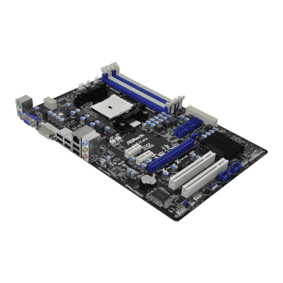
Page 11: Motherboard Layout
USB 2.0 T: USB4 B: USB5 USB 2.0 T: USB2 B: USB3 DX11 USB 2.0 Top: T: USB0 Gigabit LAN RJ-45 B: USB1 CHA_FAN2 CHA_FAN3 A55iCafe PCIE1 RoHS SATA2_1 SATA2_4 SATA2_2 AUDIO SATA2_6 SATA2_5 CODEC SATA2_3 PCIE2 PCIE3 CMOS Fast LAN... -
Page 12: I/O Panel
1.4 I/O Panel PS/2 Mouse Port (Green) USB 2.0 Ports (USB23) LAN RJ-45 Port USB 2.0 Ports (USB45) Line In (Light Blue) DVI-D Port ** 4 Front Speaker (Lime) D-Sub Port Microphone (Pink) PS/2 Keyboard Port (Purple) USB 2.0 Ports (USB01) * There are two LED next to the LAN port. -
Page 13: Installation
2. Installation This is an ATX form factor (12.0-in x 8.0-in, 30.5 cm x 20.3 cm) motherboard. Before you install the motherboard, study the configuration of your chassis to ensure that the motherboard fits into it. Pre-installation Precautions Take note of the following precautions before you install motherboard components or change any motherboard settings. -
Page 14: Cpu Installation
2.1 CPU Installation Step 1. Unlock the socket by lifting the lever up to a 90 angle. Step 2. Position the CPU directly above the socket such that the CPU corner with the golden triangle matches the socket corner with a small triangle. Step 3. -
Page 15: Installation Of Memory Modules (Dimm)
2.3 Installation of Memory Modules (DIMM) This motherboard provides four 240-pin DDR3 (Double Data Rate 3) DIMM slots, and supports Dual Channel Memory Technology. For dual channel con- figuration, you always need to install identical (the same brand, speed, size and chip-type) DDR3 DIMM pair in the slots of the same color. -
Page 16: Installing A Dimm
Installing a DIMM Please make sure to disconnect power supply before adding or removing DIMMs or the system components. Step 1. Unlock a DIMM slot by pressing the retaining clips outward. Step 2. Align a DIMM on the slot such that the notch on the DIMM matches the break on the slot. -
Page 17: Expansion Slots (Pci And Pci Express Slots)
2.4 Expansion Slots (PCI and PCI Express Slots) There are 2 PCI slots and 3 PCI Express slots on this motherboard. PCI Slots: PCI slots are used to install expansion cards that have the 32-bit PCI interface. PCIE Slots: PCIE1 / PCIE2 (PCIE x1 slot; White) is used for PCI Express cards with x1 lane width cards, such as Gigabit LAN card and SATA2 card. -
Page 18: Dual Graphics Operation Guide
2.5 AMD Dual Graphics Operation Guide This motherboard supports AMD Dual Graphics feature. AMD Dual Graphics brings multi-GPU performance capabilities by enabling an AMD A55 FCH (Hudson-D2) integrated graphics processor and a discrete graphics processor to operate simultaneously with combined output to a single display for blisteringly-fast frame ®... - Page 19 Step 7. You can also click “AMD VISION Engine Control Center” on your ® Windows taskbar to enter AMD VISION Engine Control Center. AMD VISION Engine Control Center Step 8. In AMD VISION Engine Control Center, please choose “Performance”. Click “AMD CrossFire ”.
-
Page 20: Dual Monitor And Surround Display Features
2.6 Dual Monitor and Surround Display Features Dual Monitor Feature This motherboard supports dual monitor feature. With the internal VGA output sup- port (D-Sub and DVI-D), you can easily enjoy the benefits of dual monitor feature without installing any add-on VGA card to this motherboard. This motherboard also provides independent display controllers for D-Sub and DVI-D to support dual VGA output so that D-sub and DVI-D can drive same or different display contents. - Page 21 Surround Display Feature This motherboard supports surround display upgrade. With the internal VGA output support (D-Sub and DVI-D) and external add-on PCI Express VGA cards, you can easily enjoy the benefits of surround display feature. Please refer to the following steps to set up a surround display environment: 1.
- Page 22 ® For Windows 7 / 7 64-bit / Vista / Vista 64-bit OS: Right click the desktop, choose “Personalize”, and select the “Display Settings” tab so that you can adjust the parameters of the multi-monitor according to the steps below. A.
-
Page 23: Asrock Smart Remote Installation Guide
The Multi-Angle CIR Receiver does not support Hot-Plug function. Please install it before you boot the system. * ASRock Smart Remote is only supported by some of ASRock motherboards. Please refer to ASRock website for the motherboard support list: http://www.asrock.com... -
Page 24: Jumpers Setup
2.8 Jumpers Setup The illustration shows how jumpers are setup. When the jumper cap is placed on pins, the jumper is “Short”. If no jumper cap is placed on pins, the jumper is “Open”. The illustration shows a 3-pin jumper whose pin1 and pin2 are “Short”... -
Page 25: Onboard Headers And Connectors
2.9 Onboard Headers and Connectors Onboard headers and connectors are NOT jumpers. Do NOT place jumper caps over these headers and connectors. Placing jumper caps over the headers and connectors will cause permanent damage of the motherboard! Serial ATA2 Connectors These six Serial ATA2 (SATA2) connectors support (SATA2_1: see p.11, No. -
Page 26: Front Panel Audio Header
Infrared Module Header This header supports an IRTX +5VSB optional wireless transmitting (5-pin IR1) DUMMY and receiving infrared module. (see p.11 No. 25) IRRX Consumer Infrared Module Header This header can be used to connect the remote (4-pin CIR1) controller receiver. (see p.11 No. - Page 27 RESET (Reset Switch): Connect to the reset switch on the chassis front panel. Press the reset switch to restart the computer if the computer freezes and fails to per- form a normal restart. PLED (System Power LED): Connect to the power status indicator on the chassis front panel. The LED is on when the system is operating.
- Page 28 CPU Fan Connectors Please connect the CPU fan FAN_SPEED_CONTROL CPU_FAN_SPEED cable to the connector and (4-pin CPU_FAN1) +12V match the black wire to the (see p.11 No. 4) ground pin. 1 2 3 4 Though this motherboard provides 4-Pin CPU fan (Quiet Fan) support, the 3-Pin CPU fan still can work successfully even without the fan speed control function.
- Page 29 HDMI_SPDIF Header HDMI_SPDIF header, providing SPDIF audio output to HDMI (2-pin HDMI_SPDIF1) VGA card, allows the system to see p.11 No. 27) connect HDMI Digital TV/ projector/LCD devices. Please connect the HDMI_SPDIF connector of HDMI VGA card to this header.
-
Page 30: Serial Ata (Sata) / Serial Ata2 (Sata2) Hard Disks Installation
2.10 Serial ATA (SATA) / Serial ATA2 (SATA2) Hard Disks Installation This motherboard adopts AMD A55 FCH (Hudson-D2) chipset that supports Serial ATA (SATA) / Serial ATA2 (SATA2) hard disks and RAID (RAID 0, RAID 1 and RAID 10) functions. You may install SATA / SATA2 hard disks on this motherboard for internal storage devices. -
Page 31: Sata / Sata2 Hdd Hot Plug And Hot Swap Feature And Operation Operation Guide
3. Please make sure the SATA / SATAII driver is installed into system properly. The latest SATA / SATAII driver is available on our support website: www.asrock.com 4. Make sure to use the SATA power cable & data cable, which are from our motherboard package. -
Page 32: How To Hot Plug A Sata / Sataii Hdd
How to Hot Plug a SATA / SATAII HDD: Points of attention, before you process the Hot Plug: Please do follow below instruction sequence to process the Hot Plug, improper procedure will cause the SATA / SATAII HDD damage and data loss. Step 1 Step 2 Connect SATA data cable to... -
Page 33: Driver Installation Guide
STEP 2: Make a SATA / SATAII Driver Diskette. (Please use USB floppy or floppy disk.) Insert the ASRock Support CD into your optical drive to boot your system. During POST at the beginning of system boot-up, press <F11> key, and then a window for boot devices selection appears. -
Page 34: 64-Bit / Vista
STEP 3: Use “RAID Installation Guide” to set RAID configuration. Before you start to configure RAID function, you need to check the RAID installation guide in the Support CD for proper configuration. Please refer to the BIOS RAID installation guide part of the document in the following path in the Support CD: .. -
Page 35: Tm Tm
® 2.15 Installing Windows 7 / 7 64-bit / Vista / Vista 64-bit / XP / XP 64-bit Without RAID Functions ® If you want to install Windows 7 / 7 64-bit / Vista / Vista 64-bit / XP / XP 64- bit OS on your SATA / SATAII HDDs without RAID functions, please follow below procedures according to the OS you install. -
Page 36: Tm Tm
® 2.15.2 Installing Windows 7 / 7 64-bit / Vista / Vista 64-bit Without RAID Functions ® If you want to install Windows 7 / 7 64-bit / Vista / Vista 64-bit on your SATA / SATAII HDDs without RAID functions, please follow below steps. Using SATA / SATAII HDDs with NCQ and Hot Plug functions (AHCI mode) STEP 1: Set up UEFI. -
Page 37: Uefi Setup Utility
3. UEFI SETUP UTILITY 3.1 Introduction This section explains how to use the UEFI SETUP UTILITY to configure your sys- tem. The SPI Memory on the motherboard stores the UEFI SETUP UTILITY. You may run the UEFI SETUP UTILITY when you start up the computer. Please press <F2>... -
Page 38: Navigation Keys
3.1.2 Navigation Keys Please check the following table for the function description of each navigation key. Navigation Key(s) Function Description Moves cursor left or right to select Screens Moves cursor up or down to select items + / - To change option for the selected items <Enter>... -
Page 39: Oc Tweaker Screen
3.3 OC Tweaker Screen In the OC Tweaker screen, you can set up overclocking features. EZ OC Mode You can use this option to load EZ overclocking setting. Please note that overclocing may cause damage to your components and motherboard. It should be done at your own risk and expense. - Page 40 CPU Frequency Multiplier For safety and system stability, it is not recommended to adjust the value of this item. CPU Voltage It allows you to adjust the value of CPU voltage. However, for safety and system stability, it is not recommended to adjust the value of this item. CPU NB Frequency It will display CPU NB Frequency for reference.
- Page 41 CAS# Latency (tCL) Use this item to change CAS# Latency (tCL) Auto/Manual setting. The default is [Auto]. RAS# to CAS# Delay (tRCD) Use this item to change RAS# to CAS# Delay (tRCD) Auto/Manual setting. The default is [Auto]. Row Precharge Time (tRP) Use this item to change Row Precharge Time (tRP) Auto/Manual setting.
- Page 42 Voltage Control DRAM Voltage Use this to select DRAM Voltage. The default value is [Auto]. APU PCIE Voltage VDDP Use this to select APU PCIE Voltage VDDP. The default value is [Auto]. APU DRAM PHY Voltage VDDR Use this to select APU DRAM PHY Voltage VDDR. The default value is [Auto].
-
Page 43: Advanced Screen
3.4 Advanced Screen In this section, you may set the configurations for the following items: CPU Configu- ration, Nouth Bridge Configuration, South Bridge Configuration, Storage Configura- tion, Super IO Configuration, ACPI Configuration, and USB Configuration. Setting wrong values in this section may cause the system to malfunction. -
Page 44: Cpu Configuration
3.4.1 CPU Configuration Core C6 Mode Use this item to enable or disable Core C6 mode. The default value is [Enabled]. Cstate Pmin Mode Use this item to enable or disable Cstate Pmin mode. The default value is [Disabled]. Cool ‘n’ Quiet Use this item to enable or disable AMD’s Cool ‘n’... -
Page 45: North Bridge Configuration
3.4.2 North Bridge Configuration Primary Graphics Adapter This item will switch the PCI Bus scanning order while searching for video card. It allows you to select the type of Primary VGA in case of multiple video controllers. The default value of this feature is [PCI Express]. Con- figuration options: [Onboard], [PCI] and [PCI Express]. -
Page 46: South Bridge Configuration
3.4.3 South Bridge Configuration Onboard HD Audio Select [Auto], [Enabled] or [Disabled] for the onboard HD Audio feature. If you select [Auto], the onboard HD Audio will be disabled when PCI Sound Card is plugged. Front Panel Select [Auto] or [Disabled] for the onboard HD Audio Front Panel. Onboard LAN This allows you to enable or disable the onboard LAN feature. -
Page 47: Storage Configuration
3.4.4 Storage Configuration SATA Controller Use this item to enable or disable the “SATA Controller” feature. SATA Mode Use this item to adjust SATA Mode. The default value of this option is [IDE Mode]. Configuration options: [AHCI Mode], [RAID Mode] and [IDE Mode]. If you set this item to RAID mode, it is suggested to install SATA ODD driver on SATA2_5 and SATA2_6 ports. -
Page 48: Super Io Configuration
3.4.5 Super IO Configuration Serial Port Use this item to enable or disable the onboard serial port. Serial Port Address Use this item to set the address for the onboard serial port. Configuration options: [3F8 / IRQ4] and [3E8 / IRQ4]. Infrared Port Use this item to enable or disable the onboard infrared port. -
Page 49: Acpi Configuration
3.4.6 ACPI Configuration Suspend to RAM Use this item to select whether to auto-detect or disable the Suspend-to- RAM feature. Select [Auto] will enable this feature if the OS supports it. Check Ready Bit Use this item to enable or disable the feature Check Ready Bit. Restore on AC/Power Loss This allows you to set the power state after an unexpected AC/power loss. - Page 50 ACPI HPET table Use this item to enable or disable ACPI HPET Table. The default value is [Enabled]. Please set this option to [Enabled] if you plan to use this moth- ® erboard to submit Windows Vista certification.
-
Page 51: Usb Configuration
3.4.7 USB Configuration USB 2.0 Controller Use this item to enable or disable the use of USB 2.0 controller. Legacy USB Support Use this option to select legacy support for USB devices. There are four confi guration options: [Enabled], [Auto], [Disabled] and [UEFI Setup Only]. The default value is [Enabled]. -
Page 52: Hardware Health Event Monitoring Screen
3.5 Hardware Health Event Monitoring Screen In this section, it allows you to monitor the status of the hardware on your system, including the parameters of the CPU temperature, motherboard temperature, CPU fan speed, chassis fan speed, and the critical voltage. CPU Fan 1 &... -
Page 53: Boot Screen
3.6 Boot Screen In this section, it will display the available devices on your system for you to config- ure the boot settings and the boot priority. Setup Prompt Timeout This shows the number of seconds to wait for setup activation key. 65535(0xFFFF) means indefi nite waiting. -
Page 54: Security Screen
3.7 Security Screen In this section, you may set or change the supervisor/user password for the system. For the user password, you may also clear it. -
Page 55: Exit Screen
3.8 Exit Screen Save Changes and Exit When you select this option, it will pop-out the following message, “Save configuration changes and exit setup?” Select [OK] to save the changes and exit the UEFI SETUP UTILITY. Discard Changes and Exit When you select this option, it will pop-out the following message, “Discard changes and exit setup?”... -
Page 56: Software Support
Click on a specific item then follow the installation wizard to install it. 4.2.4 Contact Information If you need to contact ASRock or want to know more about ASRock, welcome to visit ASRock’s website at http://www.asrock.com; or you may contact your... - Page 57 Installing OS on a HDD Larger Than 2TB in AHCI Mode ® This motherboard is adopting UEFI BIOS that allows Windows OS to be installed on a large size HDD (>2TB). Please follow below procedure to install the operating system. ®...
-
Page 58: Installing Os On A Hdd Larger Than 2Tb In Raid Mode
Installing OS on a HDD Larger Than 2TB in RAID Mode ® This motherboard is adopting UEFI BIOS that allows Windows OS to be installed on a large size HDD (>2TB). Please follow below procedure to install the operating system. ®... - Page 59 7. And then key in drvcfg –s [Drv number] [Ctrl number] to enter Raid Utility. For example: key in drvcfg –s 4E B5. 8. Choose Logical Drive Main Menu to set up Raid Drive. 9. Choose Logical Drive Create Menu to create a Raid Drive. 10.
- Page 60 11. Press Space on keyboard to toggle checkbox. 12. Choose Ld Size setting, and key in the Raid size. 13. After set up Raid size, please click Start to Create. 14. Press <F10> to exit Utility. 15. During reboot, please press <F11> to enter Boot Manual. Choose UEFI: SCSI CD/DVD Drive.
- Page 61 ® 16. Follow Windows Installation Guide to install OS. ® If you install Windows 7 64-bit / Vista 64-bit in a large hard disk (ex. Disk ® volume > 2TB), it may take more time to boot into Windows or install driver/ utilities.
- Page 62 B. Disable “Volume Shadow Copy” service. a. Type “computer management” in the Start Menu, then press “Enter”. b. Go to “Services and Applications>Services”; Then double click “Volume Shadow Copy”. c. Set “Startup type” to “Disable” then Click “OK”.
- Page 63 C. Reboot your system. D. After reboot, please start to install motherboard drivers and utilities. ® Windows 7 64-bit: A. Please request the hotfix KB2505454 thru this link: http://support.microsoft.com/kb/2505454/ ® B. After installing Windows 7 64-bit, install the hotfix kb2505454. (This may take long time;...
Need help?
Do you have a question about the A55iCafe and is the answer not in the manual?
Questions and answers