ASROCK UTX-111 User Manual
Hide thumbs
Also See for UTX-111:
- User manual (33 pages) ,
- Settings manual (2 pages) ,
- Settings manual (2 pages)

Related Manuals for ASROCK UTX-111


Summary of Contents for ASROCK UTX-111
- Page 1 UTX-110 UTX-111 User Manual Version 1.0 Published December 2014 Copyright©2014 ASRock INC. All rights reserved.
- Page 2 (including damages for loss of profits, loss of business, loss of data, interruption of business and the like), even if ASRock has been advised of the possibility of such damages arising from any defect or error in the documentation or product.
-
Page 3: Table Of Contents
Contents 1 Introduction ............5 1.1 Package Contents ............5 1.2 Specifications ..............6 1.3 Motherboard Layout ............8 1.4 I/O Panel ................ 10 2 Installation ............11 2.1 Screw Holes ..............11 2.2 Pre-installation Precautions ........... 11 2.3 Installation of Memory Modules (SO-DIMM) ....12 2.4 Expansion Slots (mini-PCIe and mini-PCIe/mini-SATA Slots) ................ - Page 4 4 Software Support ..........33 4.1 Install Operating System ..........33 4.2 Support CD Information ..........33 4.2.1 Running Support CD ..........33 4.2.2 Drivers Menu ............33 4.2.3 Utilities Menu............33 4.2.4 Contact Information ..........33...
-
Page 5: Introduction
In case any modifications of this manual occur, the updated version will be available on ASRock website without further notice. You may find the latest VGA cards and CPU support lists on ASRock website as well. ASRock website http://www.asrock.com If you require technical support related to this motherboard, please visit our website for specific information about the model you are using. -
Page 6: Specifications
Optional E3845/3815 Quad/Single Core Processor ® Intel new Atom Baytrail-I Supports Hyper-Threading Technology Processor Default J1900 Quad Core Processor (UTX-111) System Optional N2930/2807 Quad/Dual Core Processor Core (By CPU, Max 4) Number Max Speed (By CPU) L2 Cache (By CPU) - Page 7 Ethernet 10/100/1000 Mbps ® Ethernet Controller 2 x Intel Connector 2 x RJ-45 Max Data SATA Transfer SATA2 (3.0Gb/s) Rate HDMI 2 (1 x HDMI, 1 x Micro HDMI) DisplayPort 0 Ethernet 1 x USB 3.0 Compliant, 1 x USB2.0 Rear I/O Compliant 1 x micro USB 2.0 SMT type connector...
-
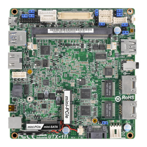
Page 8: Motherboard Layout
1.3 Motherboard Layout 2 3 4 1213 14 PNL_PWR1 COM2 BLT_VOL1 PWR_JP1 CLRMOS1 JGPIO_PWR1 BLT_PWM1 BKT_PWR1 PWRBTN1 USB2_2 COM1 BLT_PWR1 JGPIO1 BUZZ1 SET_CM1 JGPIO_SET1 DDR3 (Support DDR3L Only) RESET1 USB3_1 USB2_1 AUDIO1 VGA1 LAN2 HDMI2 LAN1 MSATA_SEL1 DC_JACK1 mini-PCIe / mini-SATA SATAII_1 SATA_PWR1 Industrial... - Page 9 1 : Backlight Control Level (BLT_PWM1) 2 : Clear CMOS Header 3 : Backlight Power Select (LCD_BLT_VCC) (BKT_PWR1) 4 : 2-Pin Buzzer Header 5 : Backlight & Amp Volume Control (BLT_VOL1) 6 : Inverter Power Control Wafer (BLT_PWR1) 7 : LVDS Panel Connector 8 : COM1 Pin9 PWR Setting 9 : Panel Power Select (LCD_VCC) (PNL_PWR1) 10 : COM Port Header (COM2)
-
Page 10: I/O Panel
1.4 I/O Panel LAN RJ-45 Port (LAN1) USB 2.0 Port (USB2_1) LAN RJ-45 Port (LAN2) Reset Button 3.5mm Audio Jack (CTIA Standard) Power Button HP-R HP-L Micro USB 2.0 Port (USB2_2) Micro HDMI Port (HDMI2) USB 3.0 Port (USB3_1) DC Jack Port (+12V Only) HDMI Port (HDMI1) -
Page 11: Installation
Chapter 2: Installation This is a 111.76 x 116.84 mm form factor motherboard. Before you install the moth- erboard, study the configuration of your chassis to ensure that the motherboard fits into it. Make sure to unplug the power cord before installing or removing the motherboard. -
Page 12: Installation Of Memory Modules (So-Dimm)
2.3 Installation of Memory Modules (SO-DIMM) UTX-110 / UTX-111 provides one 204-pin DDR3 (Double Data Rate 3) SO-DIMM slot, which supports single channel DDR3L SDRAM only. Step 1. Align a SO-DIMM on the slot such that the notch on the SO-DIMM matches the break on the slot. -
Page 13: Expansion Slots (Mini-Pcie And Mini-Pcie/Mini-Sata Slots)
2.4 Expansion Slots (mini-PCIe and mini-PCIe/mini-SATA Slots) There is 1 mini-PCIe slot and 1 mini-PCIe/mini-SATA slot on this motherboard. mini-PCIe slot: MINI_PCIE1 (mini-PCIe slot; half size) is used for PCI Express mini cards. mini-PCIe/mini-SATA slot: MINI_PCIE2 (mini-PCIe/mini-SATA slot; full size) is used for PCI Ex- press mini cards or mSATA cards. -
Page 14: Jumpers Setup
2.5 Jumpers Setup The illustration shows how jumpers are setup. When the jumper cap is placed on pins, the jumper is “Short”. If no jumper cap is placed on pins, the jumper is “Open”. The illustration shows a 3-pin jumper whose pin1 and pin2 are “Short”... - Page 15 Backlight Power Select Use this to set up the backlight (LCD_BLT_VCC) power of the LVDS connector. 1-2: +5V (3-pin BKT_PWR1) 2-3: +12V (see p.8 No. 3) Backlight Control Level 1-2: +3V 2-3: +5V (3-pin BLT_PWM1) (see p.8 No. 1) COM1 Pin9 PWR Setting 1-2: +5V 2-3: +12V (3-pin SET_CM1)
-
Page 16: Onboard Headers And Connectors
2.6 Onboard Headers and Connectors Onboard headers and connectors are NOT jumpers. Do NOT place jumper caps over these headers and connectors. Placing jumper caps over the headers and connectors will cause permanent damage of the motherboard! SATA2 Connector This Serial ATA2 (SATA2) connector supports SATA data (SATAII_1: see p.8, No. - Page 17 LVDS Connector Signal Name Signal Name LCD_VCC LCD_VCC (40-pin LVDS1) (see p.8 No. 7) LVDS_A_DATA0# LVDS_A_DATA0 GND1 LVDS_A_DATA1# LVDS_A_DATA1 GND6 LVDS_A_DATA2# LVDS_A_DATA2 GND2 LVDS_A_DATA3# LVDS_A_DATA3 GND7 LVDS_A_CLK# LVDS_A_CLK GND3 LVDS_B_DATA0# LVDS_B_DATA0 GND8 LVDS_B_DATA1# LVDS_B_DATA1 GND4 LVDS_B_DATA2# LVDS_B_DATA2 DPLVDD_EN LVDS_B_DATA3# LVDS_B_DATA3 GND5 LVDS_B_CLK# LVDS_B_CLK...
- Page 18 Inverter Power Control Wafer Signal Name (6-pin BLT_PWR1) (see p.8 No. 6) CON_LBKLT_CTL CON_LBKLT_EN LCD_BLT_VCC LCD_BLT_VCC Chassis Intrusion Headers This motherboard supports CASE OPEN detection feature (2-pin CI1) that detects if the chassis cover (see p.8 No. 16) Signal has been removed. This feature (2-pin CI2) requires a chassis with chassis (see p.8 No.
-
Page 19: Uefi Setup Utility
Chapter 3: UEFI SETUP UTILITY 3.1 Introduction This section explains how to use the UEFI SETUP UTILITY to configure your system. The UEFI chip on the motherboard stores the UEFI SETUP UTILITY. You may run the UEFI SETUP UTILITY when you start up the computer. Please press <F2>... -
Page 20: Navigation Keys
3.1.2 Navigation Keys Please check the following table for the function description of each navigation key. Navigation Key(s) Function Description Moves cursor left or right to select Screens Moves cursor up or down to select items + / - To change option for the selected items <Enter>... -
Page 21: Advanced Screen
3.3 Advanced Screen In this section, you may set the configurations for the following items: CPU Configu- ration, Chipset Configuration, Storage Configuration, Super IO Configuration, ACPI Configuration and USB Configuration. Setting wrong values in this section may cause the system to malfunction. Instant Flash Instant Flash is a UEFI flash utility embedded in Flash ROM. -
Page 22: Cpu Configuration
3.3.1 CPU Configuration Intel SpeedStep Technology Intel SpeedStep technology is Intel’s new power saving technology. Pro- cessors can switch between multiple frequencies and voltage points to en- able power saving. The default value is [Enabled]. Configuration options: ® [Enabled] and [Disabled]. If you install Windows 7 / 8 / 8.1 and want to enable this function, please set this item to [Enabled]. -
Page 23: Chipset Configuration
3.3.2 Chipset Configuration Share Memory Configure the size of memory that is allocated to the integrated graphics processor when the system boots up. Active LVDS Use this to enable or disable the LVDS. The default value is [Disabled]. Panel Type Selection This option appears only when you enable Active LVDS. -
Page 24: Storage Configuration
3.3.3 Storage Configuration SATA Controller(s) Use this item to enable or disable the SATA Controller feature. SATA Mode Selection Use this to select SATA mode. Configuration options: [IDE Mode] and [AHCI Mode]. The default value is [AHCI Mode]. AHCI (Advanced Host Controller Interface) supports NCQ and other new features that will improve SATA disk perfor- mance but IDE mode does not have these advantages. -
Page 25: Super Io Configuration
3.3.4 Super IO Configuration COM1 Configuration Use this to set parameters of COM1. Select COM1 port type: [RS232], [RS422] or [RS485]. COM2 Configuration Use this to set parameters of COM2. WDT Timeout Reset This allows users to enable/disable the Watch Dog Timer timeout to reset system. -
Page 26: Acpi Configuration
3.3.5 ACPI Configuration Suspend to RAM Use this item to select whether to auto-detect or disable the Suspend-to- RAM feature. Select [Auto] will enable this feature if the OS supports it. ACPI HPET Table Use this item to enable or disable ACPI HPET Table. The default value is [Enabled]. -
Page 27: Usb Configuration
3.3.6 USB Configuration Intel USB 3.0 Mode ® Select Intel USB 3.0 controller mode. Set [Smart Auto] to keep the USB 3.0 driver enabled after rebooting (USB 3.0 is enabled in BIOS). Set [Auto] to automatically enable the USB 3.0 driver after entering the OS (USB 3.0 is disabled in BIOS). -
Page 28: Hardware Health Event Monitoring Screen
3.4 Hardware Health Event Monitoring Screen In this section, it allows you to monitor the status of the hardware on your system, including the parameters of the CPU temperature, motherboard temperature, CPU fan speed, chassis fan speed, and the critical voltage. Case Open Feature This allows you to enable or disable case open detection feature. -
Page 29: Security Screen
3.5 Security Screen In this section, you may set, change or clear the supervisor/user password for the system. Supervisor Password Set or change the password for the administrator account. Only the ad- ministrator has authority to change the settings in the UEFI Setup Utility. Leave it blank and press enter to remove the password. -
Page 30: Boot Screen
3.6 Boot Screen In this section, it will display the available devices on your system for you to config- ure the boot settings and the boot priority. Fast Boot Fast Boot minimizes your computer’s boot time. There are three con- figuration options: [Disabled], [Fast] and [Ultra Fast]. - Page 31 Boot Beep Select whether the Boot Beep should be turned on or off when the system boots up. Please note that a buzzer is needed. Full Screen Logo Use this item to enable or disable OEM Logo. The default value is [Enabled]. CSM (Compatibility Support Module) Enable to launch the Compatibility Support Module.
-
Page 32: Exit Screen
3.7 Exit Screen Save Changes and Exit When you select this option, it will pop-out the following message, “Save configuration changes and exit setup?” Select [OK] to save the changes and exit the UEFI SETUP UTILITY. Discard Changes and Exit When you select this option, it will pop-out the following message, “Discard changes and exit setup?”... - Page 33 Click on a specific item then follow the installation wizard to install it. 4.2.4 Contact Information If you need to contact ASRock or want to know more about ASRock, you’re welcome to visit ASRock’s website at http://www.asrock.com; or you may con-...
Need help?
Do you have a question about the UTX-111 and is the answer not in the manual?
Questions and answers