ASROCK 960GM/U3S3 FX User Manual
Amd 760g/sb710 chipset
Hide thumbs
Also See for 960GM/U3S3 FX:
- Installation manual (17 pages) ,
- Quick installation manual (173 pages)

Related Manuals for ASROCK 960GM/U3S3 FX


Summary of Contents for ASROCK 960GM/U3S3 FX
-
Page 1: User Manual
960GM/U3S3 FX User Manual Version 1.0 Published December 2011 Copyright©2011 ASRock INC. All rights reserved. 1 1 1 1 1... - Page 2 (including damages for loss of profits, loss of business, loss of data, interruption of business and the like), even if ASRock has been advised of the possibility of such damages arising from any defect or error in the manual or product.
-
Page 3: Table Of Contents
Installation of Memory Modules (DIMM) ........16 Expansion Slots (PCI and PCI Express Slots) ......17 Dual Monitor and Surround Display Features ......18 ASRock Smart Remote Installation Guide ......... 21 Jumpers Setup ................22 Onboard Headers and Connectors ..........23 SATAII Hard Disk Setup Guide ........... - Page 4 3 . 3 . 3 . 3 . BIOS S BIOS S BIOS S BIOS SETUP UTILITY ETUP UTILITY ETUP UTILITY ETUP UTILITY ........................................37 BIOS S ETUP UTILITY ..........Introduction ................37 3.1.1 BIOS Menu Bar ............... 37 3.1.2 Navigation Keys ..............
-
Page 5: Introduction Introduction
In case any modifications of this manual occur, the updated version will be available on ASRock website without further notice. You may find the latest VGA cards and CPU support lists on ASRock website as well. ASRock website http://www.asrock.com If you require technical support related to this motherboard, please visit our website for specific information about the model you are using. -
Page 6: Specifications
1 . 2 1 . 2 1 . 2 Specifications Specifications Specifications 1 . 2 1 . 2 Specifications Specifications - Micro ATX Form Factor: 9.6-in x 7.8-in, 24.4 cm x 19.8 cm Platform - Solid Capacitor for CPU power - Support for Socket AM3+ processors - Support for Socket AM3 processors: AMD Phenom II X6 /... - Page 7 - CPU, VCCM, NB Voltage Multi-adjustment - Drivers, Utilities, AntiVirus Software (Trial Version), Support CD AMD OverDrive Utility, CyberLink MediaEspresso 6.5 Trial, ASRock Software Suite (CyberLink DVD Suite - OEM and Trial; ASRock MAGIX Multimedia Suite - OEM) 7 7 7 7 7...
- Page 8 - FCC, CE, WHQL - ErP/EuP Ready (ErP/EuP ready power supply is required) (see CAUTION 18) * For detailed product information, please visit our website: http://www.asrock.com WARNING Please realize that there is a certain risk involved with overclocking, including adjusting the setting in the BIOS, applying Untied Overclocking Technology, or using the third- party overclocking tools.
- Page 9 SATAII mode. You can also connect SATA hard disk to SATAII connector directly. It is a user-friendly ASRock overclocking tool which allows you to surveil your system by hardware monitor function and overclock your hardware devices to get the best system performance under Windows ®...
- Page 10 - ASRock APP Charger. Simply installing the APP Charger driver, it makes your iPhone charged much quickly from your computer and up to 40% faster than before. ASRock APP Charger allows you to quickly charge many Apple devices simultaneously and even supports continuous charging when your PC enters into Standby mode (S1), Suspend to RAM (S3), hibernation mode (S4) or power off (S5).
- Page 11 Real-Time Analysis of Your Data: With the status window, you can easily recognize which data streams you are currently transferring. 15. ASRock XFast RAM fully utilizes the memory space that cannot be used ® under Windows OS 32-bit CPU. It also shortens the loading time of previously visited websites, making web surfing faster than ever.
-
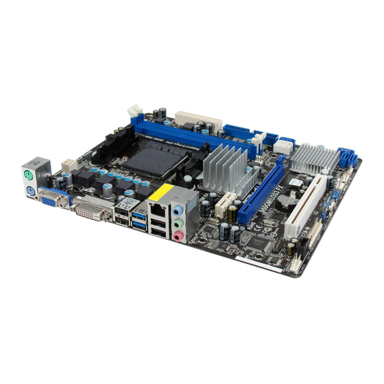
Page 12: Motherboard Layout
Top: T: USB0 RJ-45 B: USB1 USB 3.0 760G Chipset PCIE1 SATA3_1 SATA3_2 SATAII_4 (PORT 3) SATA3 6Gb/s AUDIO CODEC PCIE2 960GM/U3S3 FX RoHS CMOS BIOS SB710 BATTERY COM1 Chipset SATAII_3 (PORT 2) PCI1 SATAII_1 (PORT 0) USB6_7 PANEL 1... -
Page 13: I/O Panel
1.4 I/O P 1.4 I/O P 1.4 I/O Panel anel anel anel 1.4 I/O P 1.4 I/O P anel PS/2 Mouse Port (Green) USB 2.0 Ports (USB01) USB 2.0 Ports (USB23) USB 3.0 Ports (USB45) RJ-45 Port DVI-D Port Line In (Light Blue) D-Sub Port Line Out (Lime) PS/2 Keyboard Port (Purple) -
Page 14: Installation Installation
2. 2. 2. 2. 2. Installation Installation Installation Installation Installation This is a Micro ATX form factor (9.6-in x 7.8-in, 24.4 cm x 19.8 cm) motherboard. Before you install the motherboard, study the configuration of your chassis to en- sure that the motherboard fits into it. Pre-installation Precautions Pre-installation Precautions Pre-installation Precautions... -
Page 15: Cpu Installation
2 . 1 2 . 1 2 . 1 CPU Installation CPU Installation CPU Installation 2 . 1 2 . 1 CPU Installation CPU Installation Step 1. Unlock the socket by lifting the lever up to a 90 angle. Step 2. Position the CPU directly above the socket such that the CPU corner with the golden triangle matches the socket corner with a small triangle. -
Page 16: Installation Of Memory Modules (Dimm)
2.3 Installation of Memor y Modules (DIMM) 960GM/U3S3 FX motherboard provides two 240-pin DDR3 (Double Data Rate 3) DIMM slots, and supports Dual Channel Memory Technology. For dual channel configuration, you always need to install two identical (the same brand, speed, size and chip-type) memory modules in the DDR3 DIMM slots to activate Dual Channel Memory Technology. -
Page 17: Expansion Slots (Pci And Pci Express Slots)
2.4 Expansion Slots (PCI and PCI Express Slots) 2.4 Expansion Slots (PCI and PCI Express Slots) 2.4 Expansion Slots (PCI and PCI Express Slots) 2.4 Expansion Slots (PCI and PCI Express Slots) 2.4 Expansion Slots (PCI and PCI Express Slots) There is 1 PCI slot and 2 PCI Express slots on this motherboard. -
Page 18: Dual Monitor And Surround Display Features
2.5 Dual Monitor and Surround Display Features 2.5 Dual Monitor and Surround Display Features 2.5 Dual Monitor and Surround Display Features 2.5 Dual Monitor and Surround Display Features 2.5 Dual Monitor and Surround Display Features Dual Monitor Feature This motherboard supports dual monitor feature. With the internal dual VGA output support (DVI-D and D-Sub), you can easily enjoy the benefits of dual monitor feature without installing any add-on VGA card to this motherboard. - Page 19 3. Boot your system. Press <F2> or <Del> to enter BIOS setup. Enter “Share Memory” option to adjust the memory capability to [32MB], [64MB], [128MB] [256MB] or [512MB] to enable the function of D-sub. Please make sure that the value you select is less than the total capability of the system memory. If you do not adjust the BIOS setup, the default value of “Share Memory”, [Auto], will disable D-Sub function when the add-on VGA card is inserted to this motherboard.
- Page 20 HDCP Function HDCP function is supported on this motherboard. To use HDCP function with this motherboard, you need to adopt the monitor that supports HDCP function as well. Therefore, you can enjoy the superior display quality with high-definition HDCP encryption contents. Please refer to below instruction for more details about HDCP function.
-
Page 21: Asrock Smart Remote Installation Guide
The Multi-Angle CIR Receiver does not support Hot-Plug function. Please install it before you boot the system. * ASRock Smart Remote is only supported by some of ASRock motherboards. Please refer to ASRock website for the motherboard support list: http://www.asrock.com... -
Page 22: Jumpers Setup
2 . 7 2 . 7 2 . 7 Jumpers Setup Jumpers Setup Jumpers Setup 2 . 7 2 . 7 Jumpers Setup Jumpers Setup The illustration shows how jumpers are setup. When the jumper cap is placed on pins, the jumper is “Short”. -
Page 23: Onboard Headers And Connectors
2.8 Onboard Headers and Connectors 2.8 Onboard Headers and Connectors 2.8 Onboard Headers and Connectors 2.8 Onboard Headers and Connectors 2.8 Onboard Headers and Connectors Onboard headers and connectors are NOT jumpers. Do NOT place jumper caps over these headers and connectors. Placing jumper caps over the headers and connectors will cause permanent damage of the motherboard! •... - Page 24 USB 2.0 Headers Besides four default USB 2.0 USB_PWR ports on the I/O panel, there are (9-pin USB6_7) DUMMY two USB 2.0 headers on this (see p.12 No. 21) motherboard. Each USB 2.0 header can support two USB USB_PWR 2.0 ports. USB_PWR (9-pin USB8_9) (see p.12 No.
- Page 25 1. High Definition Audio supports Jack Sensing, but the panel wire on the chassis must support HDA to function correctly. Please follow the instruction in our manual and chassis manual to install your system. 2. If you use AC’97 audio panel, please install it to the front panel audio header as below: A.
- Page 26 Though this motherboard provides 4-Pin CPU fan (Quiet Fan) support, the 3-Pin CPU fan still can work successfully even without the fan speed control function. If you plan to connect the 3-Pin CPU fan to the CPU fan connector on this motherboard, please connect it to Pin 1-3.
-
Page 27: Sataii Hard Disk Setup Guide
2 . 9 2 . 9 2 . 9 SAT T T T T AII Hard Disk Setup Guide AII Hard Disk Setup Guide AII Hard Disk Setup Guide AII Hard Disk Setup Guide 2 . 9 2 . 9 AII Hard Disk Setup Guide Before installing SATAII hard disk to your computer, please carefully read below SATAII hard disk setup guide. -
Page 28: Installation
2 . 1 0 2 . 1 0 Serial A 2 . 1 0 Serial A Serial A Serial AT T T T T A (SA A (SA A (SA A (SAT T T T T A) / Serial A A) / Serial A A) / Serial AT T T T T AII (SA A) / Serial A... -
Page 29: Hot Plug And Hot Swap Functions For Sata / Sataii Hdds
2.12 Hot Plug and Hot Swap F 2.12 Hot Plug and Hot Swap F 2.12 Hot Plug and Hot Swap Functions for SA unctions for SA unctions for SA unctions for SAT T T T T A / SA A / SA A / SA A / SAT T T T T AII 2.12 Hot Plug and Hot Swap F... -
Page 30: Guide
SATA / SATAII / SATA3 Hot Plug support information of our motherboard is indicated in the product spec on our website: www.asrock.com 2. Make sure your SATA / SATAII / SATA3 HDD can support Hot Plug function from your dealer or HDD user manual. - Page 31 How to Hot Plug a SATA / SATAII / SATA3 HDD: Points of attention, before you process the Hot Plug: Please do follow below instruction sequence to process the Hot Plug, improper procedure will cause the SATA / SATAII / SATA3 HDD damage and data loss. Step 1 Step 2 Connect SATA data cable to...
-
Page 32: Driver Installation Guide
STEP 2: Make a SATA / SATA2 Driver Diskette. (Please use a USB floppy or floppy disk.) Insert the ASRock Support CD into your optical drive to boot your system. During POST at the beginning of system boot-up, press <F11> key, and then a window for boot devices selection appears. - Page 33 STEP 3: Use “RAID Installation Guide” to set RAID configuration. Before you start to configure RAID function, you need to check the RAID installation guide in the Support CD for proper configuration. Please refer to the BIOS RAID installation guide part of the document in the following path in the Support CD: ..
-
Page 34: Installing Windows ® Xp / Xp 64-Bit / Vista
® NOTE1. If you install Windows 7 / 7 64-bit / Vista / Vista 64-bit on IDE HDDs and want to manage (create, convert, delete, or rebuild) RAID functions on SATA / SATA2 HDDs, you still need to set up “SATA Operation Mode” to [RAID] in BIOS first. Then, please set the RAID configuration by using the Windows RAID installation guide in the following path in the Support CD: .. - Page 35 Using SATA / SATA2 / SATA3 HDDs without NCQ and Hot Plug functions (IDE mode) STEP 1: Set up BIOS. Enter BIOS SETUP UTILITY Advanced screen Storage Configuration. Set the “SATA Operation Mode” option to [IDE] for SATAII_1 to SATAII_4 ports. Set the “Onboard SATA3 Operation Mode”...
-
Page 36: Untied Overclocking Technology
2 . 1 8 2 . 1 8 Untied Overclocking T 2 . 1 8 Untied Overclocking T Untied Overclocking T Untied Overclocking Technology echnology echnology echnology 2 . 1 8 2 . 1 8 Untied Overclocking T echnology This motherboard supports Untied Overclocking Technology, which means during overclocking, FSB enjoys better margin due to fixed PCI / PCIE buses. -
Page 37: Bios S
3. 3. 3. 3. 3. BIOS SETUP UTILITY BIOS SETUP UTILITY BIOS SETUP UTILITY BIOS SETUP UTILITY BIOS SETUP UTILITY 3.1 Introduction 3.1 Introduction 3.1 Introduction 3.1 Introduction 3.1 Introduction This section explains how to use the BIOS SETUP UTILITY to configure your system. The SPI Memory on the motherboard stores the BIOS SETUP UTILITY. -
Page 38: Navigation Keys
Use [Enter], [TAB] System Time [ :00:09] or [SHIFT-TAB] to System Date [Tue 12/13/2011] select a field. BIOS Version : 960GM/U3S3 FX P1.0 Use [+] or [-] to Processor Type : AMD FX(tm)-8150 Eight-Core configure system Time. Processor (64bit) Processor Speed... -
Page 39: Oc Tweaker Screen
3 . 3 3 . 3 3 . 3 OC T OC T OC T OC Tweak weak weak weaker Screen er Screen er Screen er Screen 3 . 3 3 . 3 OC T weak er Screen In the OC Tweaker screen, you can set up overclocking features. BIOS SETUP UTILITY Main OC Tweaker... - Page 40 AMD Turbo Core Technology This item appears only when the processor you adopt supports this feature. Use this to select enable or disable AMD Turbo Core Technology. Confi guration options: [Auto] and [Disabled]. The default value is [Auto]. AMD IO C-State Support This allows you to enable or disable AMD IO C-State Support.
- Page 41 NB Frequency Multiplier For safety and system stability, it is not recommended to adjust the value of this item. CPU NB Voltage It allows you to adjust the value of CPU NB voltage. However, for safety and system stability, it is not recommended to adjust the value of this item. HT Bus Speed This feature allows you selecting Hyper-Transport bus speed.
- Page 42 CAS Latency (CL) Use this item to adjust the means of memory accessing. The default value is [Auto]. TRCD Use this to adjust TRCD values. The default value is [Auto]. Use this to adjust TRP values. The default value is [Auto]. TRAS Use this to adjust TRAS values.
-
Page 43: Advanced Screen
Advanced Screen Advanced Screen Advanced Screen Advanced Screen Advanced Screen In this section, you may set the configurations for the following items: CPU Configuration, Chipset Configuration, ACPI Configuration, Storage Configuration, PCIPnP Configuration, SuperIO Configuration, and USB Configuration. BIOS SETUP UTILITY H/W Monitor Boot Security... -
Page 44: Cpu Configuration
3.4.1 3.4.1 CPU Configuration 3.4.1 CPU Configuration CPU Configuration CPU Configuration 3.4.1 3.4.1 CPU Configuration BIOS SETUP UTILITY Advanced CPU Configuration Cool' n' Quiet [Enabled] [Enabled] Secure Virtual Machine [Disabled] Enhanced Halt State(C1E) CPU Thermal Throttle [Auto] Select Screen Select Screen Select Item Select Item Change Option... -
Page 45: Chipset Configuration
3.4.2 3.4.2 3.4.2 Chipset Configuration Chipset Configuration Chipset Configuration 3.4.2 3.4.2 Chipset Configuration Chipset Configuration BIOS SETUP UTILITY Advanced Chipset Settings Onboard HD Audio [Disabled] Front Panel [Auto] Onboard Lan [Enabled] Primary Graphics Adapter [PCI] Internal Graphics Mode [UMA] Share Memory [Auto] Onboard HDMI HD Audio [Enabled]... -
Page 46: Acpi Configuration
3.4.3 3.4.3 3.4.3 ACPI Configuration ACPI Configuration ACPI Configuration 3.4.3 3.4.3 ACPI Configuration ACPI Configuration BIOS SETUP UTILITY Advanced ACPI Settings Select auto-detect or disable the STR feature. Suspend To RAM [Auto] [Auto] Check Ready Bit Away Mode Support [Disabled] Restore on AC / Power Loss [Power Off] Ring-In Power On... -
Page 47: Storage Configuration
3.4.4 3.4.4 Storage Configuration 3.4.4 Storage Configuration Storage Configuration Storage Configuration 3.4.4 3.4.4 Storage Configuration BIOS SETUP UTILITY Advanced Configure onboard Storage Configuration serial ATA controller. Onboard SATA Controller [Enabled] SATA Operation Mode [IDE] Onboard SATA3 Operation Mode [IDE Mode] IDE1 Master [Hard Disk] IDE1 Slave... - Page 48 TYPE Use this item to configure the type of the IDE device that you specify. Configuration options: [Not Installed], [Auto], [CD/DVD], and [ARMD]. [Not Installed]: Select [Not Installed] to disable the use of IDE device. [Auto]: Select [Auto] to automatically detect the hard disk drive. After selecting the hard disk information into BIOS, use a disk utility, such as FDISK, to partition and format the new IDE hard disk drives.
-
Page 49: Pcipnp Configuration
3.4.5 3.4.5 PCIPnP Configuration 3.4.5 PCIPnP Configuration PCIPnP Configuration PCIPnP Configuration 3.4.5 3.4.5 PCIPnP Configuration BIOS SETUP UTILITY Advanced Value in units of PCI Advanced PCI / PnP Settings clocks for PCI device latency timer PCI Latency Timer [32] register. PCI IDE BusMaster [Enabled] Select Screen... -
Page 50: Super Io Configuration
3 . 4 . 6 3 . 4 . 6 Super IO Configuration 3 . 4 . 6 Super IO Configuration Super IO Configuration Super IO Configuration 3 . 4 . 6 3 . 4 . 6 Super IO Configuration BIOS SETUP UTILITY Advanced Configure Super IO Chipset... -
Page 51: Usb Configuration
3 . 4 . 7 3 . 4 . 7 USB Configuration 3 . 4 . 7 USB Configuration USB Configuration USB Configuration 3 . 4 . 7 3 . 4 . 7 USB Configuration BIOS SETUP UTILITY Advanced USB Configuration To enable or disable the onboard USB controllers. -
Page 52: Hardware Health Event Monitoring Screen
Hardware Health Event Monitoring Screen Hardware Health Event Monitoring Screen Hardware Health Event Monitoring Screen Hardware Health Event Monitoring Screen Hardware Health Event Monitoring Screen In this section, it allows you to monitor the status of the hardware on your system, including the parameters of the CPU temperature, motherboard temperature, CPU fan speed, chassis fan speed, and the critical voltage. -
Page 53: Boot Screen
Boot Screen Boot Screen Boot Screen Boot Screen Boot Screen In this section, it will display the available devices on your system for you to config- ure the boot settings and the boot priority. BIOS SETUP UTILITY Main OC Tweaker Advanced H/W Monitor Boot... -
Page 54: Security Screen
3 . 7 3 . 7 Security Screen 3 . 7 Security Screen Security Screen Security Screen 3 . 7 3 . 7 Security Screen In this section, you may set or change the supervisor/user password for the system. For the user password, you may also clear it. BIOS SETUP UTILITY Security Main... -
Page 55: Exit Screen
3.8 Exit Screen Exit Screen Exit Screen Exit Screen Exit Screen BIOS SETUP UTILITY Main OC Tweaker Advanced H/W Monitor Boot Security Exit Exit Options Exit system setup after saving the Save Changes and Exit changes. Discard Changes and Exit Discard Changes F10 key can be used for this operation. -
Page 56: Software Support Software Support
4.2.4 Contact Information Contact Information Contact Information Contact Information Contact Information If you need to contact ASRock or want to know more about ASRock, welcome to visit ASRock’s website at http://www.asrock.com; or you may contact your dealer for further information.
Need help?
Do you have a question about the 960GM/U3S3 FX and is the answer not in the manual?
Questions and answers