Table of Contents
Advertisement
Quick Links
Advertisement
Table of Contents

Related Manuals for Technogym ISOCONTROL


Summary of Contents for Technogym ISOCONTROL
- Page 1 & ERVICE MAINTENANCE MANUAL . 1.2...
- Page 3 The information contained in this document is subject to change without notice. Technogym does not guarantee this documentation in any way. Technogym shall not be held responsible for any errors contained in this manual and declines all liability for accidents or damages resulting from the supply, characteristics and use of this manual.
-
Page 5: Table Of Contents
ISOCONTROL: Service & Maintenance Manual - rev. 1.2 Contents AVVERTENZE GENERALI..........................1.1 ..............................1.1 NTRODUCTION ............................1.1 ECOMMENDATIONS ...................... 1.2 ENERAL RULES FOR REPAIR PROCEDURES TECHNICAL CHARACTERISTICS........................2.1 ........................2.1 ECHANICAL CHARACTERISTICS ........................2.1 LECTRICAL CHARACTERISTICS ..........................2.1 MBIENT SPECIFICATIONS ........................ - Page 6 ISOCONTROL: Service & Maintenance Manual - rev. 1.2 MACHINE CONFIGURATION .......................... 9.1 ........................9.1 ERVICE MENU CONFIGURATION Machine code ............................9.1 Rom range ............................9.2 Start position ............................9.2 Pacer speed ............................9.3 Time-out di attesa del cambio lato ....................... 9.4 Enabling TGS messages ........................
-
Page 7: Avvertenze Generali
1. AVVERTENZE GENERALI 1.1. INTRODUCTION This document is reserved for Technogym Service technicians, and is intended to provide authorized personnel with the necessary information to correctly carry out repairs and maintenance. A thorough knowledge of the technical information contained in this manual is essential for completing the professional training of the operator. -
Page 8: General Rules For Repair Procedures
1. Always mark any parts or positions which may be confused with each other at the time of reassembly. 2. Use original Technogym spare parts and lubricants of the recommended brands. 3. Use special tools where specified. 4. Consult the Technical Newsletters, which may contain more up-to-date information on adjustments and maintenance than those contained in this manual. -
Page 9: Technical Characteristics
ISOCONTROL: Service & Maintenance Manual - rev. 1.2 2. TECHNICAL CHARACTERISTICS The Isocontrol is an upgrade component for Selection Line machines and Element machines consisting of 5 parts: • Control panel; • Signal/power supply cable; • Encoder/pulley assembly; • Fixing assembly;... -
Page 10: Product Code
ISOCONTROL: Service & Maintenance Manual - rev. 1.2 2.5. PRODUCT CODE PERSONAL SELECTION PERSONAL SELECTION ELEMENT LUXURY CLASSIC MACHINE & PERFORMANCE ELEMENT+ CLASSIC SELECTION BEAUTY Abdominal Crunch EICM908-GD# EICM908-GG# EICMA01-GG# Abductor EICM906-GD# EICM906-GG# EICMA01-GG# Adductor EICM906-GD# EICM906-GG# EICMA01-GG# Arm Curl... -
Page 11: Wiring Diagram
ISOCONTROL: Service & Maintenance Manual - rev. 1.2 2.6. WIRING DIAGRAM 1 PULLEY All Element machines, for Selection machines refer to paragraph 5.2.2.2 “Pulleys to replace on Selection machines”. Patch POWER SUPPLY conn. 2 ISO-01 ISO-03 ENCODER Patch BOARD conn. 1... -
Page 12: Wiring
ISOCONTROL: Service & Maintenance Manual - rev. 1.2 2.6.1. IRING ISO-01: Signal/power supply cable Display board – Patch connectors Display Signal Color Patch Patch board conn. 2 conn. 1 Ground Black Faston Power supply from power supply Violet Faston (+9 Vdc) -
Page 13: Principles Of Operation
ISOCONTROL: Service & Maintenance Manual - rev. 1.2 3. PRINCIPLES OF OPERATION 3.1. BLOCK DIAGRAM The block diagram of the device is illustrated in the figure below: DISPLAY PANEL POWER SUPPLY ENCODER PULLEY BOARD 3.1.1. ISPLAY PANEL Its individual components are described separately below: DISPLAY BOARD This is the heart of the device, from which all of its functions are controlled. -
Page 14: Encoder Board
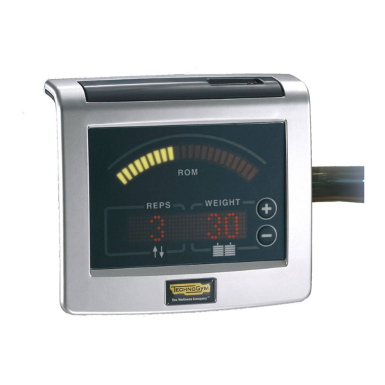
ISOCONTROL: Service & Maintenance Manual - rev. 1.2 The following components are mounted on the display board: • LED display: used for displaying the ROM arc and other information (scrolling messages, weight, repetitions, sets, etc.) • Two LEDs for the TGS (green and red): the green LED serves as its power indicator, while the red LED signals that a read or write operation is in progress on the TGS key. -
Page 15: Accessori
ISOCONTROL: Service & Maintenance Manual - rev. 1.2 4. ACCESSORI 4.1. SERIAL CABLE FOR PC CONNECTION The machine can be connected to a PC for updating the software or configuration parameters by means of the RJ45 jack situated on the lower edge of the display panel. -
Page 16: Electrical Connection
ISOCONTROL: Service & Maintenance Manual - rev. 1.2 4.2. ELECTRICAL CONNECTION 4.2.1. IRECT CONNECTION MACHINE with ISOCONTROL POWER SUPPLY Description Code 0WR00542AA Power supply 0WR00539AA-EU Italian plug English plug 0WR00539AA-UK US/Japanese plug 0WR00539AA-US 4.2.2. AISY CHAIN MACHINE MACHINE MACHINE MACHINE... -
Page 17: Installation Instructions
Isocontrol system, and which can be ordered with code 0SM00389AA-M1 (Selection) or 0SM00400AA-M1 (Element). Open the box containing the Isocontrol components and place them on the ground next to the machine on which the system is being installed. -
Page 18: Preparing Selection Machines Frames That Require Drilling
ISOCONTROL: Service & Maintenance Manual - rev. 1.2 5.2.1. REPARING ELECTION MACHINES FRAMES THAT REQUIRE DRILLING Removing the frame caps: 1. Using a flat-blade screwdriver, remove the plugs from the frame holes for passage of the cables at the power inlet and the display. -
Page 19: Procedure For Selection Machines
ISOCONTROL: Service & Maintenance Manual - rev. 1.2 5.2.2. ROCEDURE FOR ELECTION MACHINES Cable passage: 1. Using an 8-mm hex wrench, remove the machine pulley (or pulleys) that need to be replaced with those supplied in the upgrade kit. To identify the pulley (or two pulleys) that need to be removed, refer to the pulleys indicated al paragrafo 5.2.2.2... - Page 20 ISOCONTROL: Service & Maintenance Manual - rev. 1.2 and fit the rear cap on the bracket as illustrated in the figure. Photo 5.2-6 6. Secure the back of the display and the rear cap using the 4 screws c supplied in the kit.
- Page 21 ISOCONTROL: Service & Maintenance Manual - rev. 1.2 Pulley assembly: Reassemble the pulley (or the two pulleys) removed previously, replacing the rear housing and the pulley with those supplied in the kit. Take care to assemble the pulley so that...
-
Page 22: Templates For Selection Machine Frames Which Require Drilling
ISOCONTROL: Service & Maintenance Manual - rev. 1.2 5.2.2.1 Templates for Selection machine frames which require drilling MODEL M857 - M957 Abdominal Crunch M818 - M918 Abductor M817 - M917 Adductor M843 - M892 - M992 Arm Curl M845 - M945... - Page 23 ISOCONTROL: Service & Maintenance Manual - rev. 1.2 MODEL B he hole must be drilled at about 392 mm from the upper part of the top (see dimensions in the figure), on the flat inner portion of the elliptical tubing, at the centre point.
- Page 24 ISOCONTROL: Service & Maintenance Manual - rev. 1.2 MODEL E The hole must be drilled about 262 mm from the upper part of the top (see dimensions in the figure), on the flat inner portion of the elliptical tubing, at the centre point.
-
Page 25: Pulleys To Replace On Selection Machines
ISOCONTROL: Service & Maintenance Manual - rev. 1.2 MODEL H The hole must be drilled about 42 mm to the left of the pulley support welded to the frame (see dimension in the figure), on the flat inner portion of the elliptical tubing, at the centre point. - Page 26 ISOCONTROL: Service & Maintenance Manual - rev. 1.2 Lat Machine M912 Leg Curl M810-M890-M990 Leg Extension M836-M891-M991 Leg Press M851-M951 Lower Back M858-M958 Multi Hip M867-M967 Pagina 5.10...
- Page 27 ISOCONTROL: Service & Maintenance Manual - rev. 1.2 Pulley M814-M914 Rotary Calf M815-M915 Rotary Torso M850-M950 Total Abdominal M883-M983 MACHINES WHICH REQUIRE REPLACING TWO PULLEYS Arm Curl M843-M892-M992 Arm Extension M845-M945 Pagina 5.11...
- Page 28 ISOCONTROL: Service & Maintenance Manual - rev. 1.2 Chest Incline M865-M965 Chest Press M870-M970 Delts Machine M821-M921 Low Row M880-M980 Pectoral Machine M813-M913 Pulldown M849-M949 Pagina 5.12...
- Page 29 ISOCONTROL: Service & Maintenance Manual - rev. 1.2 Shoulder Press M869-M969 Upper Back M846-M946 Vertical Traction M871-M971 Pagina 5.13...
-
Page 30: Preparing Element Machines Frames That Require Drilling
LEMENT MACHINES FRAMES THAT REQUIRE DRILLING Referring to the following tables, determine where to drill the frame to prepare the machine for mounting the Isocontrol, depending from the model of machine. The numbered arrows refer to more detailed instructions provided in the text below. - Page 31 ISOCONTROL: Service & Maintenance Manual - rev. 1.2 LEG PRESS machine figure viewed from behind. Photo 5.2-12 LOW ROW machine figure viewed from the front. Photo 5.2-13 Pagina 5.15...
- Page 32 ISOCONTROL: Service & Maintenance Manual - rev. 1.2 ALL OTHER MODELS machine figure viewed from behind. Photo 5.2-14 Before starting to work on the machine... WARNING: Place cloths or some other protection on the guide bars and any other parts that may be damaged by the drill shavings.
- Page 33 ISOCONTROL: Service & Maintenance Manual - rev. 1.2 Drill the hole for the encoder cable, indicated by arrow 1 in the preceding drawings, as described below: • Drill the hole on either the front or rear side of the upper machine tubing, as specified in the table to paragraph 5.2.4.1 “Template for...
- Page 34 ISOCONTROL: Service & Maintenance Manual - rev. 1.2 below: • Use a 35-mm hole saw to drill the upper hole at the position indicated for arrow 3. • Use a 3-mm bit to drill the lower hole at the position indicated for arrow 3.
- Page 35 ISOCONTROL: Service & Maintenance Manual - rev. 1.2 • Using a 35-mm hole saw, drill a hole centered on the two abovementioned points, in order to obtain a "figure eight" inside the contours of the encoder plate drawn previously • Use a file to remove any burrs from the machine frame.
-
Page 36: Procedure For Element Machines
ISOCONTROL: Service & Maintenance Manual - rev. 1.2 5.2.4. ROCEDURE FOR LEMENT MACHINES 1. Using a flat-blade screwdriver, remove the plug from the frame hole for passage of the cable at the power inlet. Photo 5.2-21 2. Remove the “lens plug”, indicated in the... - Page 37 ISOCONTROL: Service & Maintenance Manual - rev. 1.2 6. Fix the plate which hold the encoder using the same screw that fix the pulley, placing it in horizontal position as indicated in the picture to side. Take care to insert a 2 mm spacer...
- Page 38 ISOCONTROL: Service & Maintenance Manual - rev. 1.2 7. Pass the cable supplied in the kit through the tubing, by first inserting the power supply input connector through the hole at the top of the frame, on the weight stack arch, and then pulling out the connectors for the display (Photo 5.2-27) and power supply input...
- Page 39 ISOCONTROL: Service & Maintenance Manual - rev. 1.2 13. Fix the bracket on the frame of the machine, using the screw E previously used to fix the “lens plug”. Photo 5.2-30 14. Secure the back of the display on the rear cap using 4 of the screws 1 supplied in the kit.
-
Page 40: Template For Element Machine Frames Which Require Drilling
ISOCONTROL: Service & Maintenance Manual - rev. 1.2 16. Secure the front display to the rear housing using the 4 screws 1 supplied in the kit. Photo 5.2-33 5.2.4.1 Template for Element machine frames which require drilling HOLE SIDE Abdominal Crunch MA65... -
Page 41: First Power-On
ISOCONTROL: Service & Maintenance Manual - rev. 1.2 5.3. FIRST POWER-ON After completing the installation procedure, the machine is ready to be powered up. Proceed as follows to switch on the machine: 1. Connect the mains lead to the power inlet socket on the machine. - Page 42 ISOCONTROL: Service & Maintenance Manual - rev. 1.2 Page intentionally left blank Pagina 5.26...
-
Page 43: Troubleshooting
ISOCONTROL: Service & Maintenance Manual - rev. 1.2 6. TROUBLESHOOTING The troubleshooting procedures are shown in the form of flow charts. In order to facilitate consultation, the following standard box shapes are used. This type of box is the START point of the troubleshooting procedure. It typically contains a description of the problem or malfunction. -
Page 44: Test Procedure
ISOCONTROL: Service & Maintenance Manual - rev. 1.2 6.1. TEST PROCEDURE 6.1.1. LED T To carry out the test: 1. Access the service menu as described in paragraph 9.1. “Service menu configuration”. 2. Wait for the menu to reach the “LED Test” function of paragraph 9.1.7. -
Page 45: The Display Fails To Illuminate
ISOCONTROL: Service & Maintenance Manual - rev. 1.2 6.2. THE DISPLAY FAILS TO ILLUMINATE The problem may be due to absence of the power supply or to a malfunction of the display board. THE DISPLAY FAILS TO ILLUMINATE Plug the machine into... - Page 46 ISOCONTROL: Service & Maintenance Manual - rev. 1.2 Connect the power supply jack to patch connector 2 and place the tester probes across the fastons on the back of the connector itself. The measured value should be approximately 9 Vdc.
-
Page 47: The Rom Is Not Read Or Is Read Incorrectly
ISOCONTROL: Service & Maintenance Manual - rev. 1.2 6.3. THE ROM IS NOT READ OR IS READ INCORRECTLY This error can be caused by an incorrect machine configuration, or problems with the encoder signal. THE ROM IS NOT DETECTED OR... - Page 48 ISOCONTROL: Service & Maintenance Manual - rev. 1.2 Are the pulley cogs and the Clean the dirty sensors on the encoder board components clean? Do the pulses reach the input to Replace the display the display board? board Do the pulses reach patch...
- Page 49 ISOCONTROL: Service & Maintenance Manual - rev. 1.2 Does the power supply reach Replace cable ISO-03 patch connector 1? Is the power supply at the Replace cable ISO-02 output of the display board or ISO-01 correct? Replace the display board Follow the procedure step by step to correctly diagnose the problem.
- Page 50 ISOCONTROL: Service & Maintenance Manual - rev. 1.2 Place the tester probes: • Across pins 5 and 4 of connector CN1 (or across pins 3 and 2 of connector CN2, if testing the near encoder board) of the display board. The measured value should be approximately 0.9 or 4.8 Vdc when the pulley is stationary, and approximately 2.3 Vdc...
-
Page 51: The Machine Does Not Read The Tgs
ISOCONTROL: Service & Maintenance Manual - rev. 1.2 6.4. THE MACHINE DOES NOT READ THE TGS If the machine fails to read the TGS or the green LED of the reader is off when the machine is in stand by, replace the display board. - Page 52 ISOCONTROL: Service & Maintenance Manual - rev. 1.2 Page intentionally left blank Pagina 6.36...
-
Page 53: Disassembly Of Components
ISOCONTROL: Service & Maintenance Manual - rev. 1.2 7. DISASSEMBLY OF COMPONENTS 7.1. DISASSEMBLING THE DISPLAY 1. Turn off the machine and unplug the mains lead from the wall outlet. 2. Back off the 4 screws a using a medium Philips screwdriver. -
Page 54: Disassembling The Display Components
ISOCONTROL: Service & Maintenance Manual - rev. 1.2 7.2. DISASSEMBLING THE DISPLAY COMPONENTS Carry out the procedure described in paragraph 7.1. “Disassembling the display”. With the display placed on a work bench: 1. Back off the 4 screws a using a medium Philips screwdriver. -
Page 55: Disassembling The Encoder Board On Selection Machines
ISOCONTROL: Service & Maintenance Manual - rev. 1.2 7.3. DISASSEMBLING THE ENCODER BOARD ON SELECTION MACHINES 1. Disconnect the cable (ISO-03) which comes out from behind the pulley and goes into the hole in the frame. 2. Back off the screw a on the pulley. Remove the front housing, the cogged pulley and the rear housing comprising the encoder board. -
Page 56: Disassembling The Encoder Board On Element Machines
ISOCONTROL: Service & Maintenance Manual - rev. 1.2 7.4. DISASSEMBLING THE ENCODER BOARD ON ELEMENT MACHINES 1. Back off the screws a, using a 4-mm hex wrench. 2. Remove the front casing. 3. Disassemble the rear casing, carrying out the procedure here above, on the rear side of the machine. - Page 57 ISOCONTROL: Service & Maintenance Manual - rev. 1.2 6. Cut the cable tie c. 7. Unplug the connector c from the encoder board. 8. Back off the 2 screws d which are securing the encoder board. Figura 7.4-3 To reassemble the encoder board, follow the above steps in reverse order.
- Page 58 ISOCONTROL: Service & Maintenance Manual - rev. 1.2 Page intentionally left blank Pagina 7.6...
-
Page 59: Adjustments
ISOCONTROL: Service & Maintenance Manual - rev. 1.2 8. ADJUSTMENTS The product does not require any adjustments. Pagina 8.1... - Page 60 ISOCONTROL: Service & Maintenance Manual - rev. 1.2 Page intentionally left blank Pagina 8.2...
-
Page 61: Machine Configuration
3. The various functions of the service menu will then sequentially appear on the display. 9.1.1. ACHINE CODE This function selects the machine on which the Isocontrol is installed. The display scrolls the MACHINE CODE message followed by: MC:182 The available options are listed in the table below:... -
Page 62: Rom Range
ISOCONTROL: Service & Maintenance Manual - rev. 1.2 To save the machine configuration, see paragraph 9.1.9. “Saving the configuration”; to exit without saving the changes made, disconnect the power supply form the machine. 9.1.2. OM RANGE This function sets up the value in cm of the default ROM amplitude which is used, prior to acquisition of the user's actual ROM, to correctly fill in the ROM LED arc on the display. -
Page 63: Pacer Speed
ISOCONTROL: Service & Maintenance Manual - rev. 1.2 MACHINE Selection Element Element+ MACHINE Selection Element Element+ ABDOMINA LOW ROW L CRUNCH LOWER ABDUCTOR BACK ADDUCTOR MULTI HIP ARM CURL PECTORAL PULL DOWN EXTENSION CHEST PULLEY INCLINE CHEST ROTARY PRESS CALF... -
Page 64: Time-Out Di Attesa Del Cambio Lato
ISOCONTROL: Service & Maintenance Manual - rev. 1.2 TORSO SHOULDER GLUTE PRESS TOTAL MACHINE ABDOMINAL LEG CURL UPPER BACK VERTICAL EXTENSION TRACTION LEG PRESS Use the “+” and “-” keys to bring up the desired value on the display. After reaching the desired value, wait 5 seconds for the system to automatically advance to the next function. -
Page 65: Enabling Tgs Messages
ISOCONTROL: Service & Maintenance Manual - rev. 1.2 Use the “+” and “-” keys to bring up the desired value on the display. After reaching the desired value, wait 5 seconds for the system to automatically advance to the next function. -
Page 66: Machines With 2 Encoder Boards (Refer To Paragraph 5.2.2.2 "Pulleys To Replace On Selection Machines".)
ISOCONTROL: Service & Maintenance Manual - rev. 1.2 9.1.8.2 Machines with 2 encoder boards (refer to paragraph 5.2.2.2 “Pulleys to replace on Selection machines”.) 1. Using only one lever at a time, perform a single repetition and check that the displacement of the weight stack in millimeters is correctly shown on the display. -
Page 67: User Menu Configuration
9.2.1. ONFIGURING THE To configure the TGS key, start the IsoControl Configurator application included in the Wellness System 5.0. The following window appears on start-up: For further information on the configuration, consult the Trainer Help 5.0. facility. -
Page 68: Language
ISOCONTROL: Service & Maintenance Manual - rev. 1.2 9.3. LANGUAGE Changing the language requires overwriting the software with a new language version via the RJ45 connector. There are 9 different software versions available: Italian UK English US English French German... -
Page 69: Scheduled Maintenance
ISOCONTROL: Service & Maintenance Manual - rev. 1.2 10. SCHEDULED MAINTENANCE To keep the machine in perfect working order and prevent the risk of malfunction, it is necessary to perform the scheduled maintenance operations described below. There are 2 basic types of maintenance operations: •... -
Page 70: Special Maintenance Operations
10.2. SPECIAL MAINTENANCE OPERATIONS These operations can only be carried out by a qualified technician specifically trained by Technogym and authorized to carry out machine installation and adjustments, as well as special maintenance operations or repairs which require special knowledge of the machine, its operation, safety systems and working procedures. - Page 72 TECHNOGYM S.p.A. Via G. Perticari, 20 47035 Gambettola (FC) ITALIA Tel.: +39-0547-650638 Fax: +39-0547-650150 e-mail: service@technogym.com 0SM00390AA-UK...
Need help?
Do you have a question about the ISOCONTROL and is the answer not in the manual?
Questions and answers