Perma Pure BALDWIN Series Instruction Manual
Classic therm-electric cooler
Hide thumbs
Also See for BALDWIN Series:
- User manual (25 pages) ,
- Instruction manual (9 pages) ,
- User manual (28 pages)
Table of Contents
Advertisement
Quick Links
Advertisement
Table of Contents

Related Manuals for Perma Pure BALDWIN Series


Summary of Contents for Perma Pure BALDWIN Series
- Page 1 NSTRUCTION ANUAL CLASSIC THERM-ELECTRIC COOLER Classic Model 225CE Perma Pure LLC Tel: 732-244-0010 P.O. Box 2105, 8 Executive Drive Tel: 800-337-3762 (toll free US) Toms River, NJ 08754 Fax: 732-244-8140 www.permapure.com Email: info@permapure.com...
-
Page 2: Table Of Contents
ABLE OF ONTENTS A: Specifications........................ 3 B: Limited Warranty......................4 C: Principle of Operation ....................5 D: Installation ........................8 E: Start-up Procedure ....................... 9 F: LED Summary......................10 G: Setpoints ........................11 H: Optional Relay Board ....................13 I: “New Jersey” Thermocouple Option ................14 J: Troubleshooting...................... -
Page 3: A: Specifications
Perma Pure LLC WARRANTY and DISCLAIMERS Perma Pure (Seller) warrants that product supplied hereunder shall, at the time of delivery to Buyer, conform to the published specifications of Seller and be free from defects in material and workmanship under normal use and service. Seller’s sole obligation and liability under this warranty is limited to the repair or replacement at its factory, at Seller’s option, of any such product which proves... - Page 4 A: S PECIFICATIONS Physical Description Single (Series) / Dual (Parallel) Channel System 2 x 5” Heat Exchangers connected in series or parallel ° 2 Active (cooled to 5 C) Heat Exchangers Operating Specifications Sample Gas Flow Range 2-5 LPM (Series configuration) 4.3-10.8 SCFH °...
-
Page 5: C: Principle Of Operation
C: P RINCIPLE OF PERATION Thank you for purchasing a Baldwin Model 225 Thermo-Electric Cooler. Baldwin’s Thermo-Electric Coolers are specifically designed for high ambient temperature & high water volume applications. Each model features an oversized heat sink and high performance thermoelectric devices for high heat removal capacity. Heat sinks used in Baldwin Thermo-Electric Coolers are made out of high heat transfer extruded aluminum with large 3/4"... - Page 6 When a positive DC voltage is applied to the n-type thermo-electric element, electrons pass from the p- to the n-type thermo-electric element and the cold side temperature will decrease as heat is absorbed. The heat absorption (cooling) is proportional to the current and the number of thermo-electric couples. This heat is transferred to the hot side of the Peltier element where it is dissipated into the heat sink and surrounding environment.
- Page 7 The sample gas is passed to the thermo-electric cooler via the heated filter sample probe and heated sample line. The thermo-electric cooler lowers the sample dew ° ° point to 5 C (41 F). As the gas cools and the moisture vapor condenses, the condensate exits the heat exchanger through the bottom drain connection.
-
Page 8: D: Installation
D: I NSTALLATION The Model 225 thermoelectric sample cooler should be installed away from heat sources in a well ventilated area of an instrument rack or enclosure. REMEMBER, ° the Model 225 can only control to 71 F DIFFERENTIAL from ambient temperature. °... -
Page 9: E: Start-Up Procedure
E: S TART ROCEDURE When connecting power to the 225 cooler, proper EARTH GROUNDING is essential. Use a 15 amp minimum, three-conductor power cord. Connect the green with yellow stripe conductor (Earthing) to the protective earthing ground lug on the 225 chassis. -
Page 10: F: Led Summary
F: LED S UMMARY The Model 225 has dual-channel front panel indicators with three LED status displays for each active channel (2 green, 1 red per channel). These indicators are arranged horizontally on the front of the cooler on their respective channel sides. °... -
Page 11: G: Setpoints
G: S ETPOINTS A. Set Point and Calibration Potentiometers 1. Disconnect power from the Model 225 Cooler before removing cover. 2. Remove the cover. Remove the Thermocouples from TB 1 and TB 8. The Thermocouple Generator should not be connected to either of the thermocouple inputs at this time. - Page 12 9. Set the Thermocouple Generator to 25o C. The middle left-hand side Green LED, D3, should be ON and the left-hand side LED, D2, should be OFF. 10. Set the Thermocouple Generator to 0o C. The left-hand side LED, D2, should be ON and the middle left-hand side Green LED, D3, should be OFF.
-
Page 13: H: Optional Relay Board
H: O PTIONAL ELAY OARD Computer Status Alarms Wire computer status Alarm Contacts to TB 2, (C, NC, NO) for the Water Slip/Ready/Failure Alarm status. Sample Pump Control a. Connect one side of Pump Motor to the LINE voltage. b. Connect the other side of the Pump Motor to TB2 NO (normally open). c. -
Page 14: I: "New Jersey" Thermocouple Option
I: “N ” T ERSEY HERMOCOUPLE PTION Some air quality management districts (e.g., those in New Jersey and Southern California) require temperature measurement of the gas stream at the outlet of the last heat exchanger on the cooler. Baldwin offers a 1/32-inch diameter hypodermic- style type K thermocouple that can be inserted into a special heat exchanger (i.e., it has a small port for insertion of the thermocouple) so the actual sample dew point temperature can be measured. -
Page 15: J: Troubleshooting
J: T ROUBLESHOOTING Symptom Check Action No LED(s) and no fan. AC power input. Ensure that AC power is connected. No LED(s) and fan on. AC input fuse on control board. Replace fuse as necessary. DC output fuse on control board. Replace fuse as necessary. - Page 16 For further service assistance, contact: Perma Pure LLC P.O. Box 2105 8 Executive Drive (08755) Toms River, NJ 08754 Tel: 800-337-3762 (toll free U.S.) Tel: 732-244-0010 Fax: 732-244-8140 Email: info@permapure.com Section K: Spare Parts...
-
Page 17: K: Spare Parts
K: S PARE ARTS Model 225 Part No. Description 3CCB-007G* Cooler, Circuit Board, Control, Power Supply, Rev.G 3CCB-014 Cooler, Relay Board OPTIONAL 2FAN-009 Fan, Muffin, 3" x 2", 115 VAC 60 Hz, 28 - 33 CFM, Ball Bearing ® 3CXD-001 Heat Exchanger: 5"... - Page 18 Model CD2 (Models 4S-225-9BCD2, 4S-225-9ECD2) Part No. Description 3KFA-001 Filter Assembly, Sample in-line, 2-micron 3FHG-001 Filter Bowl, Glass 3FEC-002** Filter Element: Ceramic, 2-micron 3KPB-003 Peristaltic Pump: Dual, Kit, 115V Complete w/ Enclosure 2PBM-003 Peristaltic Pump: Head Only, Standard 2PBM-001 Peristaltic Pump: Motor Only, 115V AC 60 Hz 2PBT-002PK Peristaltic Pump: Tubing, Norprene, Size 17 (10 feet) 3KPA-002*...
-
Page 19: Appendix A: Model 225
A: M PPENDIX ODEL... - Page 27 B: S PPENDIX AMPLE ONDITIONING YSTEM...
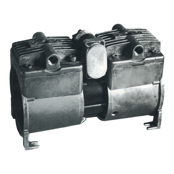
- Page 35 AIR DIMENSIONS INCORPORATED 1371 West Newport Center Dr., Suite 101, Deerfield Beach, FL 33442 - Phone 954-428-7333 or 800-423-6464 Fax 954-360-0987 http://www.airdimensions.com e-mail address -Info@AirDimensions.com MINI DIA-VAC® MAINTENANCE AND DISASSEMBLY INSTRUCTIONS A. General Operations Characteristics 1. Normal motor coil temperatures may be 160 - 180 degrees F. Winding insulation is Class B. Please note the two fans are different, so before removing the fans, note which side they belong on.
- Page 36 *Diaphragms require close precision tolerance, therefore only ADI diaphragms should be used as replacements. C. Disassembly of Head Section and Service Diaphragm 1. Remove head section by unscrewing the four large bolts. A flat-bladed screw driver may be needed to gently pry the head free of the service diaphragm. **If you have Teflon coating on the heads use caution not to scratch the surface.
- Page 37 E. Related Torque Values 1. Head bolts - 110 inch pounds. 2. Valve body screws and Diaphragm plate screws - 70 inch pounds Dia-Vac® is a Registered Trademark of Air Dimensions Inc.
- Page 41 1. Single Pump Head Loading Note: Use only MASTERFLEX Precision Tubing with MASTERFLEX Pumps to insure optimum performance. Use of other tubing may void applicable warranties. Contents: One pump head, one 15 in (38 cm) length of silicone tubing, one mounting hardware package, manual and tubing loading key. Supplied tubing loading key required for assembly.
- Page 42 Set contains four #8-32 screws, four washers, and four wingnuts. Number of heads Cold- rolled steel Stainless steel To be mounted Order number Order number MN-07013-02 MN-07013-04 MN-07013-03 MN-07013-05 MN-07013-03 MN-07013-08 MN-07013-07 MN-07013-09 2. Multi-Channel Mounting Flat bladed screwdriver required for mounting. Tubing loading key required for mounting.
- Page 43 CHART OF VOLUME PERCENT WATER CONCENTRATIONS AT SATURATION FOR VARIOUS TEMPERATURES AT STANDARD PRESSURE (ATMOSPHERIC PRESSURE) DEGREES C DEGREES F VOLUME % DEGREES C DEGREES F VOLUME % +100 + 212 100.00 + 36 0.696 + 90 + 194 69.20 + 34 0.649 + 80...
- Page 44 MOISTURE CONVERSION TABLE VAPOR PRESSURE DEWPOINT PPM on VOLUME RELATIVE (WATER/ICE in PPM on WEIGHT BASIS at 760 mm HUMIDITY EQUALIBRIUM) BASIS in AIR of Hg PRESSURE at 70 F mm MERCURY -110 -166 .0000010 .00132 .0000053 .00082 -108 -162 .0000018 .00237 .0000096...
Need help?
Do you have a question about the BALDWIN Series and is the answer not in the manual?
Questions and answers