Table of Contents
Advertisement
Quick Links
Advertisement
Table of Contents

Related Manuals for Perma Pure HORIBA Baldwin Series


Summary of Contents for Perma Pure HORIBA Baldwin Series
- Page 1 HORIBA NSTRUCTION ANUAL CLASSIC THERMO-ELECTRIC COOLERS Model M225HHD Version 4.07 Perma Pure LLC Tel: 732-244-0010 8 Executive Dr, PO Box 2105 Tel: 800-337-3762 (toll free US) Toms River, NJ 08754 Fax: 732-244-8140 www.permapure.com Email: info@permapure.com...
-
Page 2: Table Of Contents
ABLE OF ONTENTS A: Specifications........................ 4 B: Limited Warranty......................5 C: Principle of Operation ....................6 D: Installation ........................9 E: Start-up Procedure ..................... 10 F: LED Indicators ......................11 G: I/O Terminal Block Description................... 12 H: Test & Adjustment Procedures................... 13 I: Description of Options.................... -
Page 3: A: Specifications
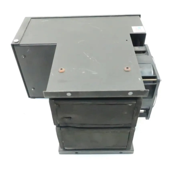
A: S PECIFICATIONS Physical Description Single (Series) / Dual (Parallel) Channel System 2 x 5” Heat Exchangers connected in series or parallel ° 2 Active (cooled to 4 C) Heat Exchangers LCD temperature display (optional) Operating Specifications Sample Gas Flow Range 3-5 LPM 6.5-10.8 SCFH °... -
Page 4: B: Limited Warranty
Perma Pure LLC WARRANTY and DISCLAIMERS Perma Pure (Seller) warrants that product supplied hereunder shall, at the time of delivery to Buyer, conform to the published specifications of Seller and be free from defects in material and workmanship under normal use and service. Seller’s sole obligation and liability under this warranty is limited to the repair or replacement at its factory, at Seller’s option, of any such product which proves... -
Page 5: C: Principle Of Operation
For gas analyzers where water vapor is an interferent, a stable, repeatable dewpoint becomes a part of the gas analyzer performance specification. Perma Pure coolers provide this constant low water concentration, resulting in an accurate component gas measurement. - Page 6 transferred to the hot side of the Peltier element where it is dissipated into the heat sink and surrounding environment. Baldwin-Series Classic Thermo-Electric Coolers remove the moisture from the sample gas by cooling the gas as it passes through a laminar impinger (heat exchanger).
- Page 7 Particulate matter passing through the sample cooler is removed by an optional Perma Pure pre-filter, located downstream from the cooler along with an optional water slip sensor. The conditioned sample gas can then be directed to the gas analyzers.
-
Page 8: D: Installation
The condensate drain connection is a Kynar elbow (or straight), 3/8” MNPT x 1/4” barbed tube fitting. An automatic condensate drain, Perma Pure Model 3KPB-003 Peristaltic Pump, dual head, is recommended for water removal. This pump uses size 17 tubing. -
Page 9: E: Start-Up Procedure
E: S TART ROCEDURE Plug in the power cord to a properly grounded main circuit. The Ready Green LED will come on within 3 minutes, indicating the relay temperature (10°C) has been achieved. After approximately 3 minutes, the set point of +5°C. (41°F) is achieved. The sample gas flow may be started immediately after the READY Green LED comes on. -
Page 10: F: Led Indicators
F: LED I NDICATORS The Model M225 has four green and two red LED operating indicators. These indicators are arranged vertically on the front of the cooler with the right side corresponding to CH1 and the left to CH2. The bottom green LED’s indicate the READY operating temperature status, normally set for 10 C (50 F). -
Page 11: G: I/O Terminal Block Description
G: I/O T ERMINAL LOCK ESCRIPTION The I/O terminal blocks are found on the bottom panel of the cooler: TB1 is the standard analog output (low voltage DC output) for all Classic Series Thermo-Electric Coolers. Model M225 has two active 5” heat exchangers. The output is 0vdc to 2.5vdc for a temperature range of 0 C to 25 °... -
Page 12: H: Test & Adjustment Procedures
H: T & A DJUSTMENT ROCEDURES NOTE: All test and adjustment procedures have been performed at the factory. Therefore, no adjustment should be necessary. A. Main Control board (1) WARNING: Before connecting power to the cooler, be aware of the HAZARDOUS LIVE VOLTAGE on the control board. - Page 13 B. Display Board (not standard on the Model M225) (1) WARNING: Before connecting power to the cooler, be aware of the HAZARDOUS LIVE VOLTAGE on the control board. Disconnect power from the cooler before opening the swing-down "L-door". Remove display cover from the front of the swing-down "L-door".
- Page 14 For Current Output (3a) If the auxiliary analog output board is set up for current output, set the ammeter to 200ma range. Connect the ammeter to TB1 (the channel 1 current output terminal), the black lead to the negative (-) terminal and the red lead to the positive (+) terminal.
-
Page 15: I: Description Of Options
I: D ESCRIPTION OF PTIONS Baldwin™-Series Classic Series Thermo-Electric Coolers have three available options: (1) temperature display; (2) alarm relay/water slip, and (3) auxiliary analog output. Classic Series Coolers may be equipped with any one or all of the options. All external I/O connections for these options are available through the terminal blocks on the bottom of the cooler. -
Page 16: J: "New Jersey" Thermocouple Option
The “K” identifies the thermocouple itself as a type “K” thermocouple. The “-5” is the height of the heat exchangers. In addition, Perma Pure offers an optional temperature transmitter board for signal or voltage temperature output. This board has one input and two outputs per channel. -
Page 17: K: Troubleshooting
K: T ROUBLESHOOTING Symptom Check Action No LED(s) and no fan. AC power input. Ensure that AC power is connected. No LED(s) and fan on. AC input fuse on control board. Replace fuse as necessary. DC output fuse on control board. Replace fuse as necessary. - Page 18 For further service assistance, contact: Perma Pure LLC P.O. Box 2105 8 Executive Drive (08755) Toms River, NJ 08754 Tel: 800-337-3762 (toll free U.S.) Tel: 732-244-0010 Fax: 732-244-8140 Email: info@permapure.com or your local representative Section J: Troubleshooting...
-
Page 19: L: Spare Parts
L: S PARE ARTS Classic Model M225 Part No. Description 2FAN-004 Fan: Muffin, 4” x 1 ½”, 12 VDC ® 3CXD-001 Heat Exchanger: 5" Durinert 3CXG-005 Heat Exchanger: 5" Glass, threaded w/ fittings 3CXK-001 Heat Exchanger: 5" Kynar 3CXS-001 Heat Exchanger: 5" Stainless Steel 3KPE-004* Peltier Element Kit, 40 mm 1PSD-027*... -
Page 20: Appendix A: Classic Model M225Hhd
A: C M225HHD PPENDIX LASSIC ODEL... - Page 26 Perma Pure LLC Tel: 732-244-0010 8 Executive Dr, PO Box 2105 Tel: 800-337-3762 (toll free US) Toms River, NJ 08754 Fax: 732-244-8140 www.permapure.com Email: info@permapure.com...
Need help?
Do you have a question about the HORIBA Baldwin Series and is the answer not in the manual?
Questions and answers