Advertisement
Quick Links
contrel
Tipo
Codice
Type
code
3ED35G
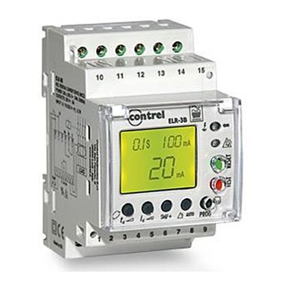
ELR-3B
con regolazione diretta / by direct setting
DESCRIZIONE GENERALE
Relè di corrente differenziale tipo B. Si associa al sensore di corrente toroidale
esterno della gamma CTB-1/xxx. Il dispositivo dispone di due relè di uscita
programmabili: relè principale di intervento e relè di segnalazione di allarme.
Dispone inoltre di una entrata per contatto libero da tensione per intervento e riarmo
da comando esterno. In esecuzione per montaggio per barra DIN 46277 o da
incasso a pannello DIN 72x72mm mediante accessorio (3EDA03). Con display
LCD permette la visualizzazione della corrente istantanea e di setup instantánea.
CONSIDERAZIONI INIZIALI
VERIFICHE ALLA RICEZIONE MATERIALI
Al ricevimento dello strumento , prima di procedere all' installazione, assicurarsi che:
- Le specifiche del dispositivo corrispondono a quanto ordinato.
- Il dispositivo risulta integro e non ha subito danni durante il trsporto.
Maggiori informazioni possono essere prelevati dal sito web: www.contrel.it
PRECAUZIONI PER LA SICUREZZA
Per una utilizzazione sicura del dispositivo è fondamentale che le persone che lo installano
e lo manipolano seguano le misure di sicurezza abituali e le avvertenze della presente guida
tecnica.
L'ELR-3B è un dispositivo progettato per l' installazione in quadro elettrico o contenitore,
con fissaggio su barra DIN o ad incasso a pannello mediante accessorio opzionale.
Dispone di un LED luminoso (ON) che indica la presenza di alimentazione ausiliaria. Nel
caso questo LED non sia acceso, verificare comunque che il dispositivo sia
effettivamente disconnesso dalla fonte di alimentazione.
INSTALLAZIONE E MESSA IN SERVIZIO
La presente guida rapida contiene informazioni ed avvertenze che l' utilizzatore deve
rispettare per garantire un funzionamento sicuro del dispositivo. L' accensione dovrà
avvenire solo un volta installato nel quadro elettrico.
!
Se si utilizza il dispositivo in modo non previsto dal costruttore, la protezione dell'
unit´potrebbe risultare compromessa.
Nel caso ci siano dubbi sul livello di sicurezza del dispositivo (presenza di danni visibili) è
necessario disconnettere l' alimentazione ausiliaria. In questo caso mettersi in contatto con
il nostro servizio di assistenza tecnica.
INSTALLAZIONE DEL DISPOSITIVO
Installazione con attacco rapido per barra DIN. Nel sensore di corrente toroidale associato
devono passare tutti i conduttori attivi che alimentano i carichi o la parte dell' impianto che si
vuole proteggere e controllare, quindi in installazioni monofase (fase e neutro, L e N), trifase
(le tre fasi, L1,L2 e L3) o trifase con neutro (L1, L2, L3 e N). Le connessioni devono essere
contenute all' interno di quadri elettrici. Si tenga presente che con lo strumento connesso l'
apertura del contenitore permette l' accesso a parti pericolose.
Lo strumento non deve essere utilizzato fino alla completa
installazione. Il circuito di alimentazione deve essere protetto
con fusibili adatti allivello di corrente assorbita dal dispositivo. In
alternativa
utilizzare un interruttore magnetotermico o
dispositivo equivalente per disconnettere la rete di
alimentazione. Per le connessioni è consigliabile una sezione
2
minima dei cavi di 1 - 1.5 mm . Una coppia di serraggio morsetti
di 0,5-0,6 N.m e una lunghezza di cavo sguainato di 7 mm.
MORSETTIERE DI CONNESSIONE
DESCRIZIONE MORSETTI
1 - 2 Ingresso per intervento e riarmo esterno
3 Non utilizzato
4 Contatto di uscita allarme - COMUNE
5 Contatto di uscita allarme - NC
6 Contatto di uscita allarme - NA
7 Non utilizzato
8 Ingresso per sensore corrente toroidale 1S1
9 Ingresso per sensore corrente toroidale 1S2
10 Alimentazione ausiliaria
(fase o neutro)
11 Alimentazione ausiliaria
(neutro o fase)
12 Non utilizzato
13 Contatto di uscita intervento - NA
14 Contatto di uscita intervento - NC
15 Contatto di uscita intervento - COMUNE
Relè di corrente differenziale tipo B -
Earth leakage relay type B -
Sensibilità (A)
Sensivity
0,03-0,1-0,3-0,5-1-3
IMPORTANTE !
52,5
Peso / Weight : 168 gr
CARACTERISTICHE
±
Optoisolata, 0.7W /230 Vca
20%
Corrente Nominale: 10 Ac.a.
Tensione Nominale: 250 Vc.a.
Carico Nominale: 2500 V·A in c.a
Corrente Nominale: 10 Ac.a.
Tensione Nominale: 250 Vc.a.
Carico Nominale: 2500 V·A in c.a
IM2150-IU v1.0
ELR-3B
ELR-3B
Ritardo intervento (s)
Tripping delay
0,1-0,2-0,3-0,4-0,5-0,75-1-5-10
con regolazione diretta / by direct setting
GENERAL DESCRIPTION
Residual Current Monitor device Type B.
transformer the
CTB-1/xxx famil
prealarm signal. It has one free voltage input for external TRIP/RESET. Mounting in DIN rail
466277 or PANEL 72x72 by means of accesories
Displays setting values and instantaneus earth leakage current value.
PRELIMINARY CONSIDERATIONS
CHECKS ON RECEPTION
On receving the instrument, check the following points:
- The unit's specifications are the same as those on your order.
- Check that the device has not suffered any damage during transport.
You can download more information from website: www.contrel.it
SAFETY PRECAUTIONS
The staff using or handling the unit must follow the common safety measures and warnings
included in the instruction manual.
The ELR-3B unit has been specifically designed for its installation in a electric board,
enclosure to a DIN rail or mounted in panel by means of accesories. It has a flashing green
LED (ON) when it is operation and, therefore, it shows that there is voltage and current in
the electronic circuit. The user must make sure that the equipment is not conected to the
power supply at all the times, even when the LED is not flashing.
INSTALLATION AND START-UP
The user must take into account and observe the informations and warnings included in this
instruction manual to guarantee the correct operation of the equipment and comply whit the
safety specifications. The equipment must not turned on until is fully installed in the
electrical panel.
!
The unit´s protections systems might not be effective if the unit is used for
purpose other than those specifications by the manufacturer.
Disconnect the equipment from the power supply when the unit´s safety protection systems
are not working or there are signs of a problem (in case of visible damage). In this case,
contact a qualified technical service or with our own technical service (TAS).
INSTALLING THE EQUIPMENT
DIN rail installation. Through the CBT must pass all live conductors supplyng electrical
energy to loads or part of the installation which requires it to earth leakage protection with
this device. In single-phase installation (phase and neutral, L and N), three phase - 3 wires
(three phases, L1, L2 and L3) or three phases - 4 wires (L1, L2, L3 and N). All connections
Should be inside t he electrical board. Please note that with the connected equipment,
67,9
43,5
quote in mm
dimensions in mm.
Fissaggio su barra DIN 46277
Fixed by rail DIN 46277
10 11
13 14 15
Reset
Test
1
2 4 5
6
8
9
Associated to external core
y. It has 2 programmables outputs relays. Main trip and
(3EDA03
IMPORTANT !
terminals and opening covers or removing elements, can
give access to dangerous parts to touch. The equipment
must not be used until it has completely finished installation.
The unit must be connected to a power supply circuit
protected by fuses in line with the range and power
consumption. In turn, the supply circuit must be provided
with a circuit breaker or equivalent device to disconnect the
equipment from the mains. During the wiring cable is
advisable a section permitted between 1 - 1.5 mm2. A
recommended torque of 0.5-0.6 N.M. Cable Stripping Tools
length 7 mm.
(EN 50022)
(EN 50022)
TERMINAL CONNECTIONS
TERMINAL DESCRIPCIÓN
1 - 2 External Input Trip / Reclose
3 Not used
4 Pre-alarm output relay common
5 Pre-alarm output relay, NC
6 Pre-alarm output relay common
7 Not used
8 Input C.B.T. 1S1
9 Input C.B.T. 1S2
10 Supply 230 Va.c. (Phase or Neutral)
11 Supply 230 Va.c. (Neutral or Phase)
12 Not used
13 Tripping output relay NO
14 Tripping output relay NC
15 Tripping output relay COMMON
balance
).
FEATURES
±
Optocoupl e d, 0.7W /230 V ac
20%
Rated current: 10 A
c.a.
Rated voltage: 250 V
c.a.
Rated Load: 2.500 V·A en AC1
Rated current: 10 A
c.a.
Rated voltage: 250 V
c.a.
Rated Load: 2.500 V·A en AC1
Advertisement

Related Manuals for Contrel ELR-3B


Summary of Contents for Contrel ELR-3B
- Page 1 The ELR-3B unit has been specifically designed for its installation in a electric board, L’ELR-3B è un dispositivo progettato per l’ installazione in quadro elettrico o contenitore, enclosure to a DIN rail or mounted in panel by means of accesories.
- Page 2 IM2150-IU v1.0 contrel ELR-3B Relè di corrente differenziale tipo B - ELR-3B Earth leakage relay type B - DESCRIPTION LED AND BUTTONS DESCRIZIONE DEGLI OPERATORI FRONTALI. - Indicazione dello stato del dispositivo mediante display LCD e due LED puntiformi. Shows equipment status via a display and 2 LED's.
- Page 3 IM2150-IU v1.0 contrel ELR-3B Relè di corrente differenziale tipo B - ELR-3B Earth leakage relay type B - CARATTERISTICHE TECNICHE. TECHNICAL FEATURES - Tipo di relé: Elettronico, classe B - Tipo Relay type: Electronic class B - Tipo di riconnessione: Manuale, mediante pulsante di RESET o mancanza alimentaz.
Need help?
Do you have a question about the ELR-3B and is the answer not in the manual?
Questions and answers