Table of Contents
Advertisement
Quick Links
Advertisement
Table of Contents

Summary of Contents for Fbt LIGHT
- Page 1 500W / 2 ZONES INSTRUCTIONS FOR USE FBT ELETTRONICA S.p.A. - Via Paolo Soprani, 1 - ZONA IND. SQUARTABUE - 62019 RECANATI (MC) - ITALY TEL. 071750591 r.a. - FAX 0717505920 - P.O. BOX 104 - E-mail: info@fbt.it - www.fbt.it...
-
Page 3: Table Of Contents
VAIE 5500 TABLE OF CONTENTS 1. WARNINGS 1.1. Power supply and earthing 1.2. Safety notes 2. INTRODUCTION 2.1. Overview of the system 2.2. Functional features 3. GENERAL DESCRIPTION 3.1. Front panel 3.2. Inside view 4. INSTALLATION AND CONNECTIONS 4.1. Wall mounting 4.2. -
Page 4: Warnings
1.2 SAFETY NOTES All FBT equipment is made according to the strictest international standards and complies with European Union requisites. For correct and effective use of the equipment it is important to be aware of all the characteristics by reading carefully these instructions and warnings. -
Page 5: Introduction
2.1 OVERVIEW OF THE SYSTEM The VAIE 5500 range includes “light” voice evacuation systems for emergency facilities, designed specifi cally for wall-mounting and equipped with control units, certifi ed in compliance with EN 54-16:2008 / EN 54-4 standards. The VAIE 5502 model is capable of managing 2 zones, each driven by a single amplifi... -
Page 6: General Description
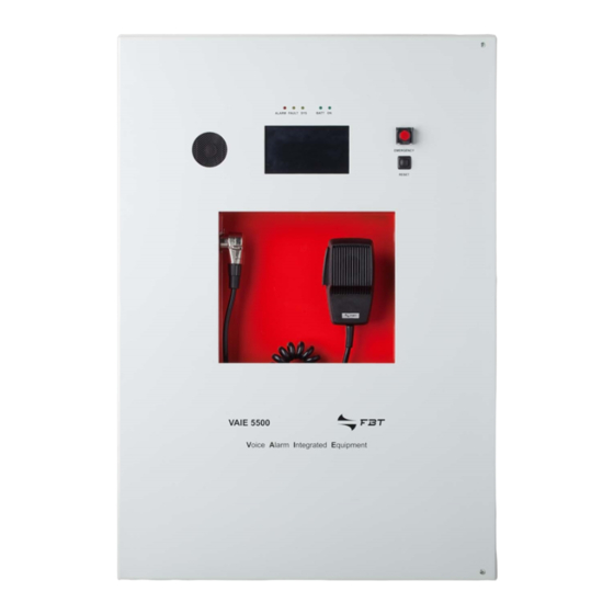
VAIE 5500 3. GENERAL DESCRIPTION 3.1 FRONT PANEL Backlit 4.3” display with touchscreen for selecting the Alert/Evacuation zones and for navigation for adjusting volume levels, confi guring the equipment and viewing failures. Integrated loudspeaker for playing back the output signals from the zones or the signals of the input sources and for replaying the acoustic signal indicating that a failure has been detected (beep). -
Page 7: Inside View
VAIE 5500 3.2 INSIDE VIEW 7 off controlled input contacts. 1 off relay output contact. Input for emergency microphone stations (max. 4). Input terminal strip for music sources. Connection to 230 VAC power supply. Connection to 24 VDC battery power. Connection of loudspeaker (zone 1). -
Page 8: Installation And Connections
VAIE 5500 4. INSTALLATION AND CONNECTIONS N.B. Please remind that the operations illustrated in this part of the manual must be carried out by specialised personnel ONLY, trained and qualifi ed in the equipment installation and maintenance. When the VAIE 5500 is opened, parts entailing a high risk of electric shocks become accessible. -
Page 9: Connections
VAIE 5500 4.2 CONNECTIONS N.B. Check that the main thermal-magnetic circuit breaker is switched OFF. If it is not, switch it OFF before carrying out any other activities in the cabinet as there is a danger of electric shocks. Proceed with connection of the various devices, referring to the appropriate points of the manual: CPU circuit Point 4.2.1 Connection of emergency units... -
Page 10: Connection Of Emergency Units
VAIE 5500 4.2.1 CONNECTION OF EMERGENCY UNITS CPU CIRCUIT Use a CAT. 5e SF/UTP cable for connecting the EMG. DESK socket (9) to the ‘IN/OUT’ sockets of the remote emergency units FMD range (max 4). 4.2.2 CONNECTION OF MUSIC INPUT CPU CIRCUIT The MUSIC terminals (10) are available for connecting outside music sources (CD player, tuner etc.). -
Page 11: Connection Of Input Contacts
VAIE 5500 4.2.3 CONNECTION OF INPUT CONTACTS CPU CIRCUIT The CONT.IN RJ45 socket (7) provides 7 controlled input contacts. An example of a connection is shown in the fi gure. 4.2.4 CONNECTION OF RELAY OUTPUT CPU CIRCUIT One relay output is available on terminals R1 (8) for signalling towards outside peripheral units. -
Page 12: Connection Of Loudspeaker Lines
VAIE 5500 4.2.5 CONNECTION OF LOUDSPEAKER LINES AMPLIFIER CIRCUIT 2-zone version, 250W without standby Terminals A/B (13) and (15) are dedicated for connection of the loudspeaker lines. 4.2.6 CONNECTION OF THE STANDBY AMPLIFIER AMPLIFIER CIRCUIT SIDE VIEW 1-zone version, 250W with standby TYPICAL CONFIGURATION 1 ZONE SYSTEM + STANDBY... -
Page 13: Connection Of Power Supplies
VAIE 5500 4.2.7 CONNECTION OF POWER SUPPLIES POWER SUPPLY AND CHARGER CIRCUITS N.B. Check that the main thermal-magnetic circuit breaker is switched OFF. If it is not, switch it OFF before carrying out any other activities in the cabinet as there is a danger of electric shocks. N.B. -
Page 14: Operational Conditions And Terminology
VAIE 5500 5. OPERATIONAL CONDITIONS AND TERMINOLOGY Following is a list of how the operating conditions of the system are signalled and of the defi nitions used on the subsequent pages of the manual, completed by indications of a general nature. 5.1 SIGNALLING OF OPERATING CONDITIONS The VAIE is designed to signal the different operating conditions as defi... -
Page 15: Menu Structure
VAIE 5500 7. MENU STRUCTURE The VAIE allows system functions to be accessed through a series of Management Panels grouped, according to their operational typology and intended use, in Option Menus accessible from the MAIN MENU window. Furthermore, the following Option Menus have been assigned to different levels of access, with reference to the various circumstances requiring different degrees of skill and authorisation of the personnel assigned. -
Page 16: Using The System
VAIE 5500 <CONFIGURATION> MENU | 3 SYSTEM LEVEL Third level of access, for instructed personnel authorised to work on the advanced functions of the system and to alter the confi guration parameters, for starting up and altering the system. The relevant login password must be entered to access this menu. To go back to the main screen press ‘Main menu’. -
Page 17: Configuration Of The System
VAIE 5500 8.1 CONFIGURATION OF THE SYSTEM Confi guration activities may be carried out only by qualifi ed personnel, suitably trained for this purpose. Password From the MUSIC MENU, go to the MAIN MENU and select < CONFIGURATION >. If access only with a password is enabled, ‘Enter confi... - Page 18 VAIE 5500 Rack confi guration In the CONFIGURATION menu, browse through the items and select ‘set>RACK CONFIG’. From here it is possible to confi gure all the basic settings of the system. D1) >> System On the ‘System confi guration’ screen page, you can set standby amplifi er. Spare amplifi...
- Page 19 VAIE 5500 D4) >> Control input Screen page for managing the inputs being controlled (1 to 7). Use the ‘Next’ and ’Prev.’ Keys to move from one input to another. Setting of the operating mode of the input (message, reset or de-activated) and of the relevant zones Mode (only if the item “Message input”...
-
Page 20: Music Menu
VAIE 5500 8.2 MUSIC MENU SETTING THE AUDIO PARAMETERS OF BGM SOURCES Screen page Description of main panel Description of options Music source control panel SELECTION OF THE BGM SOURCE displayed by the VAIE 5500 in Press the ‘Select’ key to select one of the following music sources: conditions of normal “Idle”... -
Page 21: Audio Setting> Menu
VAIE 5500 8.3 <AUDIO SETTING> MENU SETTING THE AUDIO PARAMETERS OF THE PA SOURCES Screen page Description of main panel Description of options Music and broadcast source control panel The options of the AUDIO SETTING displayed by the VAIE in conditions menu enable access to the following panels: of normal “Idle”... - Page 22 VAIE 5500 set> MONITOR SPEAKER Management of monitor speaker Sources available for selection In this panel, besides adjusting the Local microphone call volume of the monitor speaker on the Emergency unit call VAIE, input and output signals of the Music input source equipment can be played.
-
Page 23: Inspection> Menu
VAIE 5500 8.4 <INSPECTION> MENU SYSTEM STATUS INSPECTION This menu is intended for selecting options for system status inspection. It is for use by the personnel in charge of initial checking of the causes leading to a fault or to an emergency state. In this menu it is possible to select: To return to the main screen press Main menu. - Page 24 VAIE 5500 Label Category subject to diagnosis See panel Notes Primary and secondary power The diagnosis status is Power supplies supplies reported for each monitored Display management memory element. The diagnosis status is Control input Local input contacts reported for each monitored element.
- Page 25 (input active/not active). In the event of activation of one of these inputs, the system will enter an “Alarm status”, light up the ALARM LED and show automatically the panel indicating which zones are affected by the emergency (see under Activation of an automatic emergency, page 39).
-
Page 26: Operator> Menu
VAIE 5500 8.5 <OPERATOR> MENU MANAGEMENT OF EMERGENCY, FAULTY AND DISABLED CONDITIONS Menu from which to select options, to be used only by the personnel in charge of managing the system in the event of an emergency and/or a fault. If a login password was enabled at the time of confi guration, the following panel will appear: Enter the 4-digit numerical password (it is 2222 by default) and press Enter. - Page 27 VAIE 5500 Label Application See panel Notes Panel for testing the loudspeaker lines. Loudspeaker lines Loudspeaker lines On = test enabled Off = test disabled Panel for testing the local amplifi ers. Amplifi ers Amplifi ers On = test enabled Off = test disabled Panel for testing the input contacts.
- Page 28 VAIE 5500 set> CLOCK Setting of system date and time Panel for setting the system date and time. Press the following buttons: - Set date and - Set time to set these parameters. To return to the OPERATOR menu press ‘Escape’. After setting the desired date, press ‘Save date’...
-
Page 29: Configuration> Menu
VAIE 5500 8.6 <CONFIGURATION> MENU MANAGEMENT OF ADVANCED SYSTEM FUNCTIONS AND CONFIGURATION CHANGES This option selection menu is for use only by specifi cally trained personnel authorised to work on advanced system functions and to modify the confi guration parameters, for system start-up and maintenance purposes. If a login password was enabled at the time of confi... - Page 30 VAIE 5500 set> IMP. REFERENCE Impedance acquisition and tolerance setting Panel for acquiring line impedance values and setting the tolerance threshold for the diagnostic tests. Press the appropriate buttons to access the sub-panels. The Zone impedance reference panel shows the impedance values measured on the output zones, which will constitute the reference values.
- Page 31 VAIE 5500 set> EMERG. LEVELS Setting the zone volume level during emergencies Panel for adjusting the zone volume during emergencies. To return to the CONFIGURATION menu, press Escape. set> RACK CONFIG. Rack confi guration This panel contains all the parameters needed for confi guring the rack: - System.
- Page 32 VAIE 5500 Label Application See panel Notes In this panel it is possible to No. of amplifi ers set the attribution of a standby System Standby amplifi er amplifi er. The total number of amplifi ers present in the system is also shown automatically.
- Page 33 VAIE 5500 Label Application See panel Notes Panel for confi guring the controlled inputs. To go from one input to another (from 1 to 7), press Next or Prev. Press Mode to select one of the following modes: - Message input > Edit zone Setting of the messages for the zones (E = evac, A = alert, N = none)
- Page 34 VAIE 5500 set> SD CARD INSTALL Setting of zone level during emergencies The standard alert and evacuation messages and the broadcast chime are stored at the factory on the SD card mounted on the CPU circuit. In order to customise the system, it is possible, however, to add to and/or up- date these fi...
- Page 35 VAIE 5500 Password Setting a password Panel for enabling, disabling and customising the password for logging into the system service levels. The default passwords set are those shown here on the left. To change these settings and enter a new code, press the key associated with the menu in which the change is to be made and, on the next sub-panel, enter the new password.
- Page 36 VAIE 5500 <SERVICE> MENU FOR TECHNICAL ASSISTANCE OPERATORS ONLY Fourth access level, included in the CONFIGURATION menu options. Its use is permitted only to those members of the technical service personnel who have appropriate login passwords. Enter the 4-digit code of the password (this is 4444 by default) and press Enter. Upon accessing the SERVICE menu, press Service Operation.
-
Page 37: Manual Emergency - < Emergency > Menu
VAIE 5500 8.7 MANUAL EMERGENCY THE PROCEDURE FOR MANAGING EMERGENCIES IN THE MANUAL MODE (TO BE CARRIED OUT BY AN AUTHORISED OPERATOR) IS DESCRIBED BELOW. 8.7.1 GENERAL INFORMATION The manual emergency mode can be accessed at any time and has priority both over any pre-recorded messages under way - that may have been activated by an external peripheral unit connected to the controlled inputs (7) –... - Page 38 VAIE 5500 8.7.4 SENDING OUT OF A LIVE EMERGENCY NOTICE FROM REMOTE STATIONS Lift the safety lid on the station and press the EMERGENCY key once. It lights up steadily. The fact that the system has been placed in a state of emergency by the station is shown also on any other stations. Select the zones where the message should be sent.
-
Page 39: Automatic Emergency Alarm Status Activated By An External Peripheral Unit
VAIE 5500 8.8 AUTOMATIC EMERGENCY ALARM STATUS ACTIVATED BY AN EXTERNAL PERIPHERAL UNIT THE PROCEDURE FOR MANAGING AN EMERGENCY STATUS SET OFF BY AN EXTERNAL PERIPHERAL UNIT THAT ACTIVATES THE INPUT CONTACTS PROGRAMMED TO ENABLE THE “ALARM STATUS” IS DESCRIBED BELOW. 8.8.1 ACTIVATION OF AN AUTOMATIC EMERGENCY In the event of activation of a programmed input contact the VAIE 5500 stops its ‘Idle’... -
Page 40: Failure Status
VAIE 5500 9. FAILURE STATUS THE VAIE 5500 HAS DIAGNOSTIC ROUTINES THAT MONITOR CONTINUOUSLY THE AVAILABILITY OF EMERGENCY SOURCES AND THE INTEGRITY OF CRITICAL PATHS OF THE SIGNALS ENSURING SYSTEM OPERATION IN EMERGENCY CONDITIONS. 9.1 SYSTEM OPERATION AND SIGNALLING IN A GENERIC FAILURE CONDITION •... -
Page 41: Technical Specifications
VAIE 5500 10. TECHNICAL SPECIFICATIONS MODEL VAIE 5502 Rated audio output @230V 500 W / D=2,5%* typical distortion at 25 W 0,025% Rated audio output @24V 400 W / D=10%* typical distortion at 25 W 0,025% Display 4.3” , backlit with touch screen, 480x272 pixels N°... - Page 42 VAIE 5500 LIST OF OPTIONAL FUNCTIONS CLAUSE DESCRIPTION 7.6.2 Manual silencing of the voice alarm condition 7.7.2 Manual reset of the voice alarm condition Voice alarm condition output Indication of fault related to the transmission path to the CIE Indication of fault related to voice alarm zone Voice alarm manual control Interface to external control device(s) Emergency microphone(s)
- Page 44 Le informazioni contenute in questo manuale sono state scrupolosamente controllate; tuttavia non si assume nessuna responsabilità per eventuali inesattezze. La FBT Elettronica S.p.A. si riserva il diritto di modifi care le caratteristiche tecniche ed estetiche dei prodotti in qualsiasi momento e senza preavviso.
Need help?
Do you have a question about the LIGHT and is the answer not in the manual?
Questions and answers