
Subscribe to Our Youtube Channel
Related Manuals for Elsner KNX Suntracer sl basic


Summary of Contents for Elsner KNX Suntracer sl basic
- Page 1 Suntracer KNX sl basic Weather Station Item number 70156 Installation and Adjustment...
-
Page 3: Table Of Contents
6.13.2. AND logic connection inputs ..............46 6.13.3. Connection inputs of the OR logic ............. 48 Elsner Elektronik GmbH • Sohlengrund 16 • 75395 Ostelsheim • Germany Weather Station Suntracer KNX sl basic • from software version 1.00, ETS programme version 1.0... - Page 4 The change status (software version and date) can be found in the contents footer. If you have a device with a later software version, please check www.elsner-elektronik.de in the menu area "Service" to find out whether a more up-to- date version of the manual is available.
-
Page 5: Safety And Operating Instructions
Elsner Elektronik is not liable for any changes in norms and standards which may occur after publication of these operating instructions. For information on maintenance, disposal, scope of delivery and technical data, please refer to the installation instructions. -
Page 6: Installation And Start-Up
• Wind sensor monitoring: If the wind measurement value changes by less than ± 0.5 m/s within 48 hours, the maximum measurement value of 35 m/s is output as a fault message. All wind alarms with a limit value below 35 m/s become active as a result •... - Page 7 Fig. 1 There must be at least 60 cm clearance to oth- er elements (structures, construction parts, etc.) below, to the sides and in front of the de- vice. 60 cm Fig. 2 The device must be attached to a vertical wall 90°...
-
Page 8: Position Of The Sensors
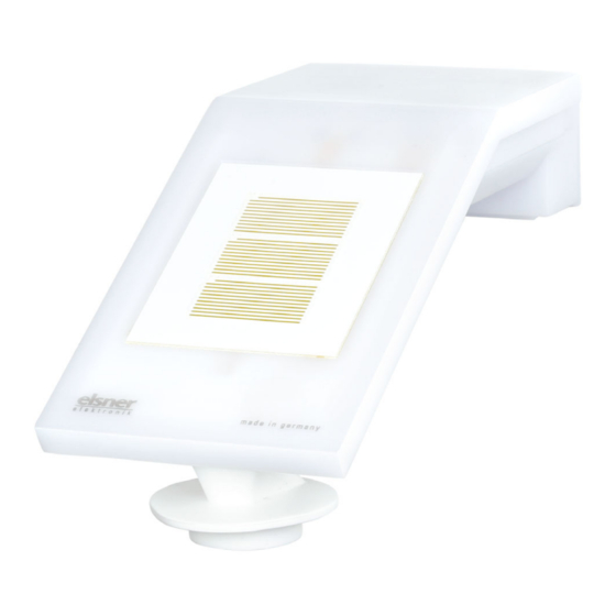
3.2. Position of the sensors Fig. 5 Brightness sensors 1-3. With alignment of the device to the south Sensor 1 = East Sensor 2 = South Sensor 3 = West For measurement direction, see chapter below Precipitation sensor (area with tracks) Position of temperature sensor Wind measuring element ATTENTION! -
Page 9: Measurement Direction Of The Brightness Sensors
3.2.1. Measurement direction of the brightness sensors Fig. 6 Sensor 1 = East, measurement directed outwards Sensor 2 = South, measurement directed vertically to the device surface Sensor 3 = West, measurement directed outwards 3.3. Installing the weather station 3.3.1. Attach mount First, assemble the mount for wall/pole mounting. -
Page 10: Assembly With Mounting Arm Fix
Pole installation The device is installed on the pole with the enclosed clamp. Fig. 8 Bottom view Pole Insert the clamp in the mount through the re- cess. Tighten the clamp on the pole. Make sure that the arrows are pointing up- ward. - Page 11 Affix sensor mounting plate: Fig. 11 (Schema sequence screw fastening) Screw the sensor mounting plate onto the boom with the countersunk screw DIN 7991 M8x10. Place the Schnorr tooth lock washers between the mounting plate and the boom Fig. 12 For mounting use the cylinder head screws DIN 912 M4x25 and place the DIN 125 washers under the screw heads.
- Page 12 Installation examples: Fig. 14 Sensor offset upwards. Fig. 15 Sensor offset downwards. Fig. 16 Sensor offset to the right (or the left). Weather Station Suntracer KNX sl basic • Status: 26.08.2021 • Errors excepted. Subject to technical changes.
-
Page 13: Attaching And Connecting The Device
3.3.3. Attaching and connecting the device Fig. 17 1. Slide the device onto the mounting from above. 2. Tighten the screw of the mount to secure the device. 3. Screw the M8 connectors of the connection cable onto the connection socket on the bottom side of the device. -
Page 14: Instructions For Assembly And Initial Start-Up
35 seconds after the power is turned on. Configuration is made using the KNX software ETS. The product file can be down- loaded from the Elsner Elektronik website on www.elsner-elektronik.de in the “Ser- vice” menu. After the bus voltage has been applied, the device will enter an initialisation phase last- ing approx. - Page 15 bottom side top side Fig. 19 Programming LED (under the semi-transparent lid) Programming button for teaching the device Weather Station Suntracer KNX sl basic • Status: 26.08.2021 • Errors excepted. Subject to technical changes.
-
Page 16: Transfer Protocol
Transfer protocol Transfer protocol Units: Temperatures in degrees Celsius Brightness in Lux Wind in metres per second 5.1. List of all communications objects Abbreviation flags: Communication Read W Write Transmit U Update Text Function Flags DPT type Size Software version Output R-CT [217.1] DPT_Version... - Page 17 Transfer protocol Text Function Flags DPT type Size Temp. threshold value 1: Switching Output R-CT [1.1] DPT_Switch 1 bit output Temp. threshold value 1: Switching Input -WC- [1.1] DPT_Switch 1 bit output block Temp. threshold value 2: Absolute Input/ RWCT [9.1] DPT_Value_Temp 2 bytes value Output Temp.
- Page 18 Transfer protocol Text Function Flags DPT type Size Brightness sensor threshold value 1: Input -WC- [7.5] DPT_TimePeriod- 2 bytes Delay from 1 to 0 Brightness sensor threshold value 1: Output R-CT [1.1] DPT_Switch 1 bit Switching output Brightness sensor threshold value 1: Input -WC- [1.1] DPT_Switch...
- Page 19 Transfer protocol Text Function Flags DPT type Size Brightness sensor 2 threshold value 1: Input -WC- [7.5] DPT_TimePeriod- 2 bytes Delay from 1 to 0 Brightness sensor 2 threshold value 1: Output R-CT [1.1] DPT_Switch 1 bit Switching output Brightness sensor 2 threshold value 1: Input -WC- [1.1] DPT_Switch...
- Page 20 Transfer protocol Text Function Flags DPT type Size Brightness sensor 3 threshold value 1: Input -WC- [7.5] DPT_TimePeriod- 2 bytes Delay from 1 to 0 Brightness sensor 3 threshold value 1: Output R-CT [1.1] DPT_Switch 1 bit Switching output Brightness sensor 3 threshold value 1: Input -WC- [1.1] DPT_Switch...
- Page 21 Transfer protocol Text Function Flags DPT type Size Total brightness threshold value 1: Input -WC- [7.5] DPT_TimePeriod- 2 bytes Delay from 1 to 0 Total brightness threshold value 1: Output R-CT [1.1] DPT_Switch 1 bit Switching output Total brightness threshold value 1: Input -WC- [1.1] DPT_Switch...
- Page 22 Transfer protocol Text Function Flags DPT type Size Twilight brightness threshold 1: delay Input -WC- [7.5] DPT_TimePeriod- 2 bytes from 1 to 0 Twilight brightness threshold value 1: Output R-CT [1.1] DPT_Switch 1 bit Switching output Twilight brightness threshold value 1: Input -WC- [1.1] DPT_Switch...
- Page 23 Transfer protocol Text Function Flags DPT type Size Wind sensor: Measurement [Beaufort] Output R-CT [20.014] DPT_Beau- 1 byte fort_Wind_Force_S- cale Wind sensor: Max. query measure- Input -WC- [1.017] DPT_Trigger 1 bit ment Wind sensor: Maximum measurement Output R-CT [9.5] DPT_Value_Wsp 2 bytes [m/s] Wind sensor: Maximum measurement...
- Page 24 Transfer protocol Text Function Flags DPT type Size Wind threshold value 4: Delay from Input -WC- [7.5] DPT_TimePeriod- 2 bytes 1 to 0 Wind threshold value 4: Switching Output R-CT [1.1] DPT_Switch 1 bit output Wind threshold value 4: Switching Input -WC- [1.1] DPT_Switch...
- Page 25 Transfer protocol Text Function Flags DPT type Size 1175 Computer 5: Input I3 Input RWCT 4 bytes 1176 Computer 5: Output O1 Output R-CT 4 bytes 1177 Computer 5: Output O2 Output R-CT 4 bytes 1178 Computer 5: Condition text Output R-CT [16.0] DPT_String_AS-...
- Page 26 Transfer protocol Text Function Flags DPT type Size 1400 Logic input 10 Input -WC- [1.2] DPT_Bool 1 bit 1401 Logic input 11 Input -WC- [1.2] DPT_Bool 1 bit 1402 Logic input 12 Input -WC- [1.2] DPT_Bool 1 bit 1403 Logic input 13 Input -WC- [1.2] DPT_Bool...
-
Page 27: Parameter Setting
Parameter setting Text Function Flags DPT type Size 1446 OR logic 1: Block Input -WC- [1.1] DPT_Switch 1 bit 1447 OR logic 2: 1-bit switching output Output R-CT [1.2] DPT_Bool 1 bit 1448 OR logic 2: 8-bit output A Output R-CT 1 byte 1449 OR logic 2: 8-bit output B... -
Page 28: Storage Of Threshold Values
Parameter setting "General settings" parameter block. The "Software version" communications object is sent once after 5 seconds. 6.0.2. Storage of threshold values For threshold values that are specified via a communication object, a starting value must be entered for the first commissioning. It is valid until the first communication of a new threshold value. -
Page 29: Temperature Measurement Value
Parameter setting Select whether the special rain output is to be used with fixed switching delay. This switching output has no delay on rain recognition and 5 minutes delay after it is dry again. Use rain output with fixed No • Yes switching delay Set the delay times. -
Page 30: Temperature Threshold Values
Parameter setting on change of 0.1°C • 0.2°C • 0.5°C • 1.0°C • 2.0°C • 5.0°C (if sent on change) Send cycle 5 s … 2 h; 10 s (if sent periodically) Select whether the minimum and maximum value should be used. Use minimum and maximum value No •... - Page 31 Parameter setting When the threshold value per communication object is specified, the starting va- lue, object value limit and type of change to the threshold value are then set. From the 1st communication onwards, the threshold value corresponds to the value of the communication object and is not multiplied by the factor 0.1.
-
Page 32: Frost Alarm
Parameter setting Block If necessary, activate the switching output block and set what a 1 or 0 at the block entry means and what happens in the event of a block. Use switching output block No • Yes Analysis of the blocking object •... -
Page 33: Brightness Measurement Value
Parameter setting Define the send pattern and the object value. Send pattern • on change • on change to frost • on change to no frost • on change and periodically • on change to frost and periodically • on change to no frost and periodically Send cycle 5 s …... -
Page 34: Brightness Threshold Values Sensor 1-3 And Brightness Threshold Values Total
Parameter setting 6.7. Brightness threshold values sensor 1-3 and brightness threshold values total Activate the required brightness threshold values at the individual sensors and at the total threshold value (in each case a maximum of four). The menus for the further set- ting of the threshold values are then displayed. - Page 35 Parameter setting With both of the methods for specifying the threshold values the hysteresis is set. Hysteresis setting in % • absolute Hysteresis in % of the threshold value 0 … 100; 50 (for setting in %) Hysteresis in Lux 0 …...
-
Page 36: Twilight Brightness Threshold Values
Parameter setting Switching output sends on change to 1 do not send message • If switching output = 1 send 1 Switching output sends on change to 0 do not send message • If switching output = 0 send 0 Switching output sends on change and Send switching output status periodically... - Page 37 Parameter setting When the threshold value per communication object is specified, the starting va- lue, object value limit and type of change to the threshold value are then set. Start threshold value in Lux 1 … 1000; 10 valid until first call Object value limit (min.) in Lux 1 …...
-
Page 38: Night
Parameter setting Action when locking • do not send message • send 0 • send 1 Action upon release [Dependent on the "Switching output (with 2 seconds release delay) sends" setting] The behaviour of the switching output on release is dependent on the value of the pa- rameter "Switching output sends"... -
Page 39: Wind Measurement
Parameter setting Set the delay for the switching and in which cases the switch output sends and which value is output at night. Delays can be set via objects No • Yes (in seconds) Switching delay on night none • 1 s … 2 h Switching delay on day none •... -
Page 40: Wind Threshold Values
Parameter setting Beaufort Meaning Fresh breeze Strong breeze High wind Gale Severe gale Storm Violent storm Hurricane 6.11. Wind threshold values Activate the wind threshold values required (maximum four) The menus for the further setting of the threshold values are then displayed. Threshold value 1 No •... - Page 41 Parameter setting When the threshold value per communication object is specified, the starting va- lue, object value limit and type of change to the threshold value are then set. From the 1st communication onwards, the threshold value corresponds to the value of the communication object and is not multiplied by the factor 0.1.
-
Page 42: Computer
Parameter setting Block If necessary, activate the switching output block and set what a 1 or 0 at the block entry means and what happens in the event of a block. Use switching output block No • Yes Analysis of the blocking object •... - Page 43 Parameter setting start-up, as the factory settings are always used until the first call (setting via objects is ignored). Maintain the input values received via communication • never objects • after power supply restoration • after power supply restoration and programming Select the function set the input mode and starting values for input 1 and input 2.
- Page 44 Parameter setting Prerequisites When querying the prerequisites set the output type and output values at different sta- tuses: Output type • 1 bit • 1 byte (0...255) • 1 byte (0%...100%) • 1 byte (0°...360°) • 2 byte counter without math. symbol •...
- Page 45 Parameter setting Calculations and transformation For calculations and transformations set the output values to the various conditions: Output value (if applicable A1 / A2) if the monitoring time period 0 [Input range depending on the type of is exceeded output] if blocked 0 [Input range depending on the type of output]...
-
Page 46: Logic
Parameter setting Monitoring period 5 s • ... • 2 h; 1 min Value of the object "monitoring status" 0 • 1 if period is exceeded If necessary, activate the computer block and set what a 1 or 0 at the block entry means and what happens in the event of a block. - Page 47 Parameter setting Each logic output may transmit one 1 bit or two 8 bit objects. Determine what the out put should send if logic = 1 and = 0. 1. / 2. / 3. / 4. Input • do not use - Logic inputs 1...16 - Logic inputs 1...16 inverted •...
-
Page 48: And Logic Connection Inputs
Parameter setting Set the output send pattern. Send pattern • on change of logic • on change of logic to 1 • on change of logic to 0 • on change of logic and periodically • on change of logic to 1 and periodically •... - Page 49 Parameter setting Logic input 1 Logic input 1 inverted Logic input 2 Logic input 2 inverted Logic input 3 Logic input 3 inverted Logic input 4 Logic input 4 inverted Logic input 5 Logic input 5 inverted Logic input 6 Logic input 6 inverted Logic input 7 Logic input 7 inverted...
-
Page 50: Connection Inputs Of The Or Logic
Parameter setting Switching output 3 Temperature Switching output 3 Temperature inverted Switching output 4 Temperature Switching output 4 Temperature inverted Brightness sensor switching output 1 Brightness sensor switching output 1 inverted Brightness sensor switching output 2 Brightness sensor switching output 2 inverted Brightness sensor switching output 3 Brightness sensor switching output 3 inverted Brightness sensor switching output 4... - Page 51 Parameter setting AND logic output 8 inverted Weather Station Suntracer KNX sl basic • Version: 26.08.2021 • Technical changes and errors excepted.
- Page 52 Elsner Elektronik GmbH Control and Automation Engineering Sohlengrund 16 75395 Ostelsheim Phone +49 (0) 70 33 / 30 945-0 info@elsner-elektronik.de Germany +49 (0) 70 33 / 30 945-20 www.elsner-elektronik.de Technical support: +49 (0) 70 33 / 30 945-250...
Need help?
Do you have a question about the KNX Suntracer sl basic and is the answer not in the manual?
Questions and answers