Table of Contents
Advertisement
Quick Links
EN
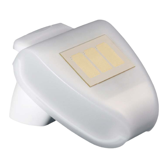
Weather Station P03/3
Replacement for P00 (3-wire), P01 and P02
for controls WS1, WS10, WS20, WS1000,
WS1000 Touch, FS100 and PS8A
Technical Specifications and Installation Instructions
Item number 30107
Elsner Elektronik GmbH Control and Automation Engineering
Sohlengrund 16
75395 Ostelsheim
Germany
Phone +49 (0) 70 33 / 30 945-0 info@elsner-elektronik.de
Fax
+49 (0) 70 33 / 30 945-20 www.elsner-elektronik.de
Technical support: +49 (0) 70 33 / 30 945-250
Advertisement
Table of Contents

Related Manuals for Elsner P03/3


Summary of Contents for Elsner P03/3
- Page 1 Item number 30107 Elsner Elektronik GmbH Control and Automation Engineering Sohlengrund 16 75395 Ostelsheim Phone +49 (0) 70 33 / 30 945-0 info@elsner-elektronik.de Germany +49 (0) 70 33 / 30 945-20 www.elsner-elektronik.de Technical support: +49 (0) 70 33 / 30 945-250...
-
Page 2: Technical Specifications
GPS receiver. Central European Time is output, daylight savings time is adjusted au- tomatically according to the specifications of central europe. Die P03/3 serves as replacement for the 3-wire P00, the P01 or the P02 for conservatory controls WS1, WS10, WS20, WS1000 and WS1000 Touch and for the facade control FS100 and evaluation unit PS8A. -
Page 3: Installation And Commissioning
Elsner Elektronik is not liable for any changes in norms and standards which may occur after publication of these operating instructions. -
Page 4: Installation Position
(structures, con- struction parts, etc.). 60 cm Fig. 2 The weather station must be mounted on a vertical wall (or a pole). Wall pole P03/3 Weather Station • Status: 09.06.2016 • Technical changes reserved. Errors reserved. -
Page 5: Mounting The Sensor
Fasten the mount vertically onto the wall or pole. Fig. 5 When wall mounting: flat side on wall, crescent- Collar shaped collar upward. P03/3 Weather Station • Status: 09.06.2016 • Technical changes reserved. Errors reserved. - Page 6 Sun, wind and precipitation can act upon the sensors without hindrance. Fig. 9 Example use of the hinge arm mounting: Fitting to a pole with worm drive hose clips P03/3 Weather Station • Status: 09.06.2016 • Technical changes reserved. Errors reserved.
- Page 7 2.3.2. View of rear side and drill hole plan Fig. 10 a+b Drill hole plan Dimensions of rear side of housing with bracket. Sub- ject to change for technical enhancement. Langloch 7,5 x 5 mm P03/3 Weather Station • Status: 09.06.2016 • Technical changes reserved. Errors reserved.
- Page 8 Connection plug 1: +24 V DC | 2: GND | 3: Data (massive cable up to 0.8 mm²) Control LED GPS recei- Socket for jumper P03/3 Weather Station • Status: 09.06.2016 • Technical changes reserved. Errors reserved.
-
Page 9: Notes On Mounting And Commissioning
Please take care not to damage the temperature sensor (small blank at the bottom part of the housing.) when mounting the weather station. Please also take care not to break P03/3 Weather Station • Status: 09.06.2016 • Technical changes reserved. Errors reserved. -
Page 10: Maintenance Of The Weather Station
ATTENTION The device can be damaged if water penetrates the housing. • Do not clean with high pressure cleaners or steam jets. P03/3 Weather Station • Status: 09.06.2016 • Technical changes reserved. Errors reserved.
Need help?
Do you have a question about the P03/3 and is the answer not in the manual?
Questions and answers