
Related Manuals for BUSCH R5 RA 1000-1600 B


Summary of Contents for BUSCH R5 RA 1000-1600 B
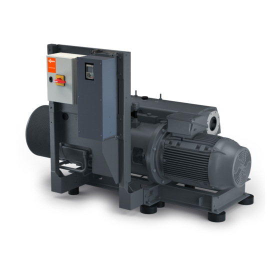
- Page 1 Installation and Retrofit Instructions R5 RA/RC 1000-1600 B Fuji Variable-Frequency Drive Installation 0870239775/-_en / Original instructions / Modifications reserved 31/08/2021...
-
Page 2: Table Of Contents
Table of Contents Table of Contents 1 Safety ............................3 2 Introduction ..........................3 3 Retrofit Kit Description ......................4 3.1 Scope of Delivery ......................4 3.1.1 Variable Frequency Drive Retrofit Kit ..............4 3.1.2 Motor Retrofit Kit ....................5 3.2 Motor Compatibility ......................5 4 Retrofit Kit Transport ........................6 5 Storage .............................7 6 Installation..........................7... -
Page 3: Safety
Safety Prior to handling the machine, this instruction manual should be read and understood. If anything needs to be clarified, please contact your Busch representative. Read this manual carefully before use and keep for future reference. This instruction manual remains valid as long as the customer does not change anything on the product. -
Page 4: Retrofit Kit Description
3 | Retrofit Kit Description Retrofit Kit Description 3.1 Scope of Delivery Different retrofit kits are available, depending on the motor type previously fitted on the machine. The retrofit kit without motor is only intended for machines having a compatible motor with the variable-frequency drive included in this kit, see Motor Compatibility [► 5]. -
Page 5: Motor Retrofit Kit
3.2 Motor Compatibility NOTICE Non-compatible motor Risk of damage to the machine and the variable-frequency drive • Make sure to use a compatible motor and approved by Busch. The variable-frequency drive is only compatible with the following motor(s): Machine Motor type... -
Page 6: Retrofit Kit Transport
4 | Retrofit Kit Transport Retrofit Kit Transport WARNING Suspended load. Risk of severe injury! • Do not walk, stand or work under suspended loads. • Check the complete kit for transport damage. WARNING Sharp edges. Risk of severe injury! •... -
Page 7: Storage
Storage | 5 Storage NOTICE Long storage time. Risk of damage to the variable-frequency drive! Due to a long storage time the capacitors of the variable-frequency drive can lose effi- ciency because of electrochemical processes. In worst case it can lead to a short circuit and therefore to a damage to the variable-frequency drive. -
Page 8: Installation Location
6 | Installation 6.1.1 Installation Location • Make sure that the electrical elements are located as below on the machine. 6.1.2 Line Protection • Make sure that the cross-section of the supply line is designed according to the trans- fer category and the maximum permitted current. The contractor commissioning the device must ensure protection for the power line. -
Page 9: Preventing Electromagnetic Interferences
Installation | 6 Cooling With integrated fans, with active cooling. NOTE: Do not cover fan/cooling outlets! 6.1.4 Preventing Electromagnetic Interferences Where possible use shielded lines for control circuits. The shielding should be applied to the line end with special care and without laying the leads across longer stretches without shielding. -
Page 10: Variable-Frequency Drive Installation
6 | Installation 6.2 Variable-Frequency Drive Installation NOTICE Sealing not correctly mounted. Loss of the protection class! • Make sure during assembly tasks to correctly mount all sealing. • Replace any worn or damaged seal. WARNING Sharp edges. Risk of severe injury! •... -
Page 11: Mechanical Assembly - Vfd And Switch Box Subset
Installation | 6 6.2.2 Mechanical Assembly - VFD and Switch Box Subset • Assemble the variable-frequency drive and the switch box subset on the vertical hold- ers, using the 6 screws and nuts provided. NOTE Make sure you use the tooth washers for grounding contact. 6.2.3 Mechanical Assembly - Thermal Protection •... -
Page 12: Electrical Connection
6 | Installation 6.3 Electrical Connection DANGER Live wires. Risk of electrical shock. • Electrical installation work must only be executed by qualified personnel. DANGER Live wires. Carry out any work on the variable-frequency drive and motor. Risk of electrical shock! •... -
Page 13: Device Connection
Installation | 6 6.3.2 Device Connection • Connect all sensors, device and ground of the above illustration, according to the ta- ble below: Pos. Device Description Cable Holder ground Control box frame grounding Drive 1 Command cable Drive 2 Communication cable Thermoswitch TSA Oil temperature switch Level LS... -
Page 14: Power Supply
6 | Installation 6.3.3 Power Supply • Inside the switch box, guide the mains connection cable through the cable gland. • Connect the cables to the terminals as follows: connect the power supply directly on the main switch terminal and the grounding wire on the PE terminal. Terminal no. -
Page 15: Customer Command
Installation | 6 6.3.4 Customer Command • Inside the switch box, guide the control cable through the EMC cable gland. • Connect the cables to the terminals as follows: Cable gland size of the power input: – M16 x 1.5 (cable Ø ► 6 … 10.5 mm) for EMC shielded cable. Pos. - Page 16 6 | Installation Terminals Functions Terminals 1 and 2 Security chain output Terminal 3 Customer start Terminal 4 PID function activation Terminals 6 and 7 Speed preset digital inputs Terminals 13 and 14 Speed analog input Terminals 15, 16 and 17 Alarm relay output Terminals 18, 19 and 20 Com.
-
Page 17: Commissioning
Commissioning | 7 NOTICE Incorrect direction of rotation. Risk of damage to the machine! • Operation in the wrong direction of rotation can destroy the machine in a short time! Prior to start-up, ensure that the machine is operated in the right direction. •... -
Page 18: Troubleshooting
The motor or the variable • Check the LED on the frequency drive (VFD) is de- variable-frequency drive fective. display, if red, it is faulty (contact Busch or read er- ror with software). 18 / 20 Installation and Retrofit Instructions R5 RA_RC 1000-1600 B_EN_en... -
Page 19: Technical Data
Technical Data | 9 Technical Data Below additional technical data once the variable-frequency drive has been installed on the motor. The technical datas of the machine in the original instruction manual remain valid after the retrofitting. RA/RC 1000-1600 B with VFD Allowed frequency range 25 …... - Page 20 Busch Vacuum Solutions We shape vacuum for you. Argentina Denmark Malaysia South Africa info@busch.com.ar info@busch.dk busch@busch.com.my info@busch.co.za Australia Finland Mexico Spain sales@busch.com.au info@busch.fi info@busch.com.mx contacto@buschiberica.es Austria France Netherlands Sweden busch@busch.at busch@busch.fr info@busch.nl info@busch.se Bangladesh Germany New Zealand Switzerland sales@busch.com.bd info@busch.de sales@busch.co.nz...
Need help?
Do you have a question about the R5 RA 1000-1600 B and is the answer not in the manual?
Questions and answers