
Subscribe to Our Youtube Channel
Related Manuals for BUSCH MINK Hydrogen


Summary of Contents for BUSCH MINK Hydrogen
- Page 1 Instruction Manual MINK Hydrogen Hydrogen Recirculation Blower MH 0018 A Ateliers Busch S.A. Zone industrielle, 2906 Chevenez Switzerland 0870220060/-0001_en / Original instructions / Modifications reserved 19/06/2020...
-
Page 2: Table Of Contents
Table of Contents Table of Contents 1 Safety ............................3 2 Product Description ........................4 2.1 Operating Principle ......................5 2.2 Application........................5 3 Transport ..........................5 4 Storage .............................6 5 Installation..........................6 5.1 Installation Conditions ...................... 6 5.2 Connecting Lines / Pipes ....................7 5.2.1 Suction Connection .................... -
Page 3: Safety
Safety Prior to handling the machine, this instruction manual should be read and understood. If anything needs to be clarified, please contact your Busch representative. Read this manual carefully before use and keep for future reference. This instruction manual remains valid as long as the customer does not change anything on the product. -
Page 4: Product Description
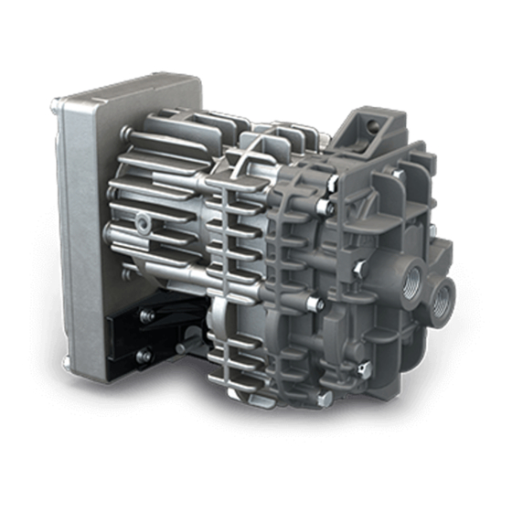
2 | Product Description Product Description 6-pole HDSCS connector (CAN) Electrical connection (+V Batt Inlet connection Lead seal Nameplate Pressure connection NOTE Technical term. In this instruction manual, we consider that the term ‘machine’ refers to the ‘com- pressor’. NOTE Illustrations In this instruction manual the illustrations may differ from the machine appearance. -
Page 5: Operating Principle
Conveying of other media leads to an increased thermal and/or mechanical load on the machine and is permissible only after a consultation with Busch. The machine is intended for the placement in a non-potentially explosive environment. -
Page 6: Storage
4 | Storage Storage • Seal all apertures with adhesive tape or reuse provided caps, if not connected to a sys- tem. If the machine is to be stored for more than 2 months: • Make sure that the inside of the process chamber will be kept dry and dust free at ambient temperature. -
Page 7: Connecting Lines / Pipes
In case of very long connection lines it is advisable to use larger line sizes in order to avoid a loss of efficiency. Seek advice from your Busch representative. • Make sure that the connections are “face sealed” and not “thread sealed” to ensure tightness. -
Page 8: Suction Connection
5 | Installation 5.2.1 Suction Connection WARNING Unprotected connection. Risk of severe injury! • Do not put hand or fingers in the connection. NOTICE Inlet gas particle size. Risk of damage to the machine! • Make sure that the inlet gas complies with ISO 12103-1, A.2 fine test dust. NOTICE Ingress of foreign objects or liquids. -
Page 9: Electrical Connection
• Electrical installation work must only be executed by qualified personnel. • Make sure that the motor of the machine will not be affected by electric or electro- magnetic disturbance from the mains; if necessary seek advice from Busch. • Electrically connect the machine •... -
Page 10: Version With Analogue Speed Control
5 | Installation 5.3.1 Version with Analogue Speed Control 1 = 0 … 5 V (= 0 … 6000 rpm) 4 = - 2 = - 5 = - 3 = CAN L (actual values) 6 = - 5.3.2 Version with CAN-Communication 1 = KL15 4 = - 2 = CAN H... -
Page 11: Motor Rotation Direction
Commissioning | 6 5.3.3 Motor Rotation Direction Commissioning NOTICE Lubricating a dry running machine (compression chamber). Risk of damage to the machine! • Do not lubricate the compression chamber of the machine with oil or grease. CAUTION During operation the surface of the machine may reach temperatures of more than 70°C. -
Page 12: Standard Version
6 | Commissioning • Measure the motor current and record it as reference for future maintenance and troubleshooting work. 6.1 Standard Version The machine starts automatically with maximum speed as soon as electrical power is supplied. 6.2 Version with Analogue Speed Control The electronic is automatically activated as soon as electrical power is supplied. - Page 13 Commissioning | 6 CAN Status Message (Actual Values) One second after startup, the machine sends every 50 ms a CAN status message with actual values. If the machine receives a CAN control message before the first second after startup the machine sends the CAN status message immediately. Power-On Bit After startup a power-on bit is set in the CAN status frame for one second.
- Page 14 6 | Commissioning Electronics limits Status and diagnostic Bit number Limit Wrong voltage 24 V motor ► 35 V Speed derating 130 … 145 °C ► rotation speed de- crease >145 °C ► motor off If Power Consumption permanently > 700W ► motor off Overload 6 and 7 700 W...
-
Page 15: Maintenance
NOTICE Remove lead seal without Busch approval. Loss of Busch liability! • Ask your Busch representative before removing the lead seal. • Shut down the machine and lock against inadvertent start up. • Vent the connected lines to atmospheric pressure. -
Page 16: Oil Draining
7 | Maintenance 7.2 Oil Draining 7.2.1 Overall Information NOTE Oil draining. Recommendation. • There is no ideal angle to put the gear for oil draining. We would recommend to move the gearbox several times from standard “vertical position” to a 90° position. The re- maining oil must be the lowest possible. -
Page 17: Draining Procedure
• Before proceeding the oil draining, make sure that the cylinder of your machine has four access holes to the motor screws. If not, do not proceed the oil draining and con- tact your Busch representative. STEP 1 • Remove the machine from the system. - Page 18 7 | Maintenance STEP 4 NOTE Oil draining. Recommendation. • There is no ideal angle to put the gear for oil draining. We would recommend to move the gearbox several times from standard “vertical position” to a 90° position. The re- maining oil must be the lowest possible.
- Page 19 Maintenance | 7 STEP 5 • 1. Check the surface cleanliness for oil traces. NOTICE Cleaning the surface. Risk of damage to the machine! • Do not use any solvant or liquid. Use only clean and dry paper or tissue! •...
- Page 20 7 | Maintenance STEP 6 • Replace the old motor nose O-ring by the new one delivered in the kit. Put grease on it then place it correctly in its groove. 20 / 40 0870220060_MH0018A_-0001_IM_en...
- Page 21 Maintenance | 7 STEP 7 NOTICE Inserting the stage into the motor. Risk of damage to the machine! • Take care and make sure not to shock or bump the stage while inserting it into the motor! • Insert gently the stage into the motor. Then insert and tighten the four M6 screws with a 5 Nm (+/-10%) screwing torque.
-
Page 22: Service Kit And Oil Type
7 | Maintenance 7.2.3 Service Kit and Oil Type Service Kit – Part number: 0990221163 – Content: Oil filling plug + Motor nose O-ring Oil Type – Fuchs Renolin Unisyn OL32 – Solvay Fomblin M07 (Depending on customers’ systems configuration) Oil has to be purchased locally by sales companies because of oil packaging. -
Page 23: Machine Stage Replacement
Maintenance | 7 7.3 Machine Stage Replacement 7.3.1 Stage Disassembly STEP 1 • If the cylinder has four holes to directly access to the motor screws, unscrew them us- ing an M5 hexagonal tool and switch to STEP 4. If not, follow the instructions de- scribed on STEPS 2 and 3. - Page 24 7 | Maintenance STEP 4 • Hold the motor while pulling up the stage (because of the resistance coming from the rotor’s magnetic force). STEP 5 • 1. Check the surface cleanliness for oil traces. NOTICE Cleaning the surface. Risk of damage to the machine! •...
- Page 25 Maintenance | 7 • 2. Remove the existing O-Ring carefully to avoid damaging the groove. • Make sure there is no burr on machined surfaces (chamfer, groove, flange surface, etc.). STEP 6 • Peel the label off (located on the backside of the motor). Do not use temperature higher than 100°C to help removing the label.
-
Page 26: Stage Replacement Package
7 | Maintenance 7.3.2 Stage Replacement Package The new stage is delivered with a kit in a plastic bag including a label with Serial Num- ber. This label must follow the stage to maintain the traceability. The plastic bag kit content is the following: •... - Page 27 Maintenance | 7 STEP 3 NOTICE Inserting the stage into the motor. Risk of damage to the machine! • Take care and make sure not to shock or bump the stage while inserting it into the motor! • Insert gently the stage into the motor. Then insert and tighten the four M6 screws with a 5 Nm (+/-10%) screwing torque.
-
Page 28: Stage Testing
7 | Maintenance 7.3.4 Stage Testing Motor start test: 100% of stages are tested at the manufacturing company and performances are stored for traceability. This test intends to guarantee that the complete blower starts properly. • Use a stabilized 500 Watts power supply. •... -
Page 29: Overhaul
• Decontaminate the machine as much as possible and state the contamination status in a ‘Declaration of Contamination’. Busch will only accept machines that come with a completely filled in and legally binding signed ‘Declaration of Contamination’ (form downloadable from www.buschvacuum.com). -
Page 30: Spare Parts
Risk of premature failure! Loss of efficiency! • The exclusive use of Busch genuine spare parts and consumables is recommended for the correct functioning of the machine and to validate the warranty. Standard spare parts kits are available for this product. -
Page 31: Can Protocol
CAN Protocol | 11 11 CAN Protocol 11.1 Standard CAN Interface 250 kBit/s 0870220060_MH0018A_-0001_IM_en 31 / 40... -
Page 32: Can Interface 500 Kbit/S
11 | CAN Protocol 11.2 CAN Interface 500 kBit/s • Baudrate 500 kb/s • Bit length 11 bit • Behaviour at CAN loss: "0" RPM • Enable signal for electronics activation "Yes" • Motor behaviour when flow request "0" → "Motor waits for signal" •... - Page 33 CAN Protocol | 11 11.5 CAN Interface 250 kBit/s, DOT Purple • Baudrate 250 kb/s • Bit length 29 bit • Behaviour at CAN loss: "0" RPM • Enable signal for electronics activation "No" • Motor behaviour when flow request "0" → "Motor waits for signal" •...
-
Page 34: Technical Data
0.10 Oil leak rate mL/1000hours Dimensions 249.5 x 120 x 199 Weight approx. High frequency transient phases (with up and down pressure levels) need to be discussed and validated between customers and Busch on applications themselves. 34 / 40 0870220060_MH0018A_-0001_IM_en... -
Page 35: 13 Tüv Certificate
TÜV Certificate | 13 13 TÜV Certificate 0870220060_MH0018A_-0001_IM_en 35 / 40... -
Page 36: Eu Declaration Of Conformity
This Declaration of Conformity and the CE-mark affixed to the nameplate are valid for the machine within the Busch scope of delivery. This Declaration of Conformity is issued under the sole responsibility of the manufacturer. When this machine is integrated into a superordinate machinery the manufacturer of the superordinate machinery (this can be the operating company, too) must conduct the conformity assessment process for the superordinate machine or plant, issue the Declaration of Conformity for it and affix the CE-mark. - Page 37 Note...
- Page 38 Note...
- Page 39 Note...
- Page 40 Chile Israel Portugal United Arab Emirates info@busch.cl service_sales@busch.co.il busch@busch.pt sales@busch.ae China Italy Romania United Kingdom info@busch-china.com info@busch.it office@buschromania.ro sales@busch.co.uk Colombia Japan Russia info@buschvacuum.co info@busch.co.jp info@busch.ru info@buschusa.com Czech Republic Korea Singapore info@buschvacuum.cz busch@busch.co.kr sales@busch.com.sg www.buschvacuum.com 0870220060/-0001_en / © Ateliers Busch S.A.
Need help?
Do you have a question about the MINK Hydrogen and is the answer not in the manual?
Questions and answers