Table of Contents
Advertisement
Trademarks
®
Autel
,
MaxiSys
®
MaxiRecorder
registered in China, the United States and other countries. All other marks
are trademarks or registered trademarks of their respective holders.
Copyright Information
No part of this manual may be reproduced, stored in a retrieval system or
transmitted, in any form or by any means, electronic, mechanical,
photocopying, recording, or otherwise without the prior written permission
of Autel.
Disclaimer of Warranties and Limitation of Liabilities
All information, specifications and illustrations in this manual are based on
the latest information available at the time of printing.
Autel reserves the right to make changes at any time without notice. While
information of this manual has been carefully checked for accuracy, no
guarantee is given for the completeness and correctness of the contents,
including but not limited to the product specifications, functions, and
illustrations.
Autel will not be liable for any direct, special, incidental, indirect damages or
any economic consequential damages (including the loss of profits).
IMPORTANT
Before operating or maintaining this unit, please read this manual carefully,
paying extra attention to the safety warnings and precautions.
For Services and Support
pro.autel.com
www.autel.com
1-855-288-3587/1-855-AUTELUS (North America)
0086-755-86147779 (China)
Support@autel.com
For technical assistance in all other markets, please contact your local
selling agent.
®
,
MaxiDAS
are trademarks of Autel Intelligent Technology Corp., Ltd.,
®
®
,
MaxiScan
i
®
,
MaxiCheck
,
and
Advertisement
Table of Contents

Related Manuals for Autel MaxiBAS BT608


Summary of Contents for Autel MaxiBAS BT608
- Page 1 All information, specifications and illustrations in this manual are based on the latest information available at the time of printing. Autel reserves the right to make changes at any time without notice. While information of this manual has been carefully checked for accuracy, no...
- Page 2 Safety Information For your own safety and the safety of others, and to prevent damage to the device and vehicles upon which it is used, it is important that the safety instructions presented throughout this manual be read and understood by all persons operating or coming into contact with the device.
- Page 3 The safety messages herein cover situations Autel is aware of. Autel cannot know, evaluate or advise you as to all of the possible hazards. You must be certain that any condition or service procedure encountered does not jeopardize your personal safety.
-
Page 4: Table Of Contents
CONTENTS SAFETY INFORMATION ................ii SAFETY MESSAGES ................ii SAFETY INSTRUCTIONS ................. ii USING THIS MANUAL ................1 ....................1 ONVENTIONS GENERAL INTRODUCTION ..............3 2.1 M BAS BT608 T ...............4 ESTER 2.1.1 Function Description ..............4 2.1.2 Power Sources ................5 2.1.3 Technical Specifications ..............6 VCI V200 —... -
Page 5: Safety Information
5.1 T ................. 25 ROCEDURE 5.2 T ..................26 ESULTS BATTERY REPLACE ................27 BATTERY RESET ................... 29 7.1 A ) ......29 EGISTRATION AFTER BATTERY REPLACEMENT 7.1.1 BMS Reset ................... 29 7.1.2 Electric Appliance Reset .............. 30 7.2 S ................ - Page 6 REMOTE DESKTOP ................52 REGISTER TOOL .................. 54 14.1 R ..............54 EGISTRATION VIA ESTER 14.2 R EGISTRATION VIA AN NTERNET ROWSER ON A OMPUTER OR OBILE ...................... 54 EVICE MAINTENANCE AND SERVICE ............55 15.1 M ............... 55 AINTENANCE NSTRUCTIONS 15.2 T ............
-
Page 7: Using This Manual
Using This Manual This manual contains device usage instructions. Some illustrations shown in this manual may contain modules and optional equipment that are not included in your system. Contact your sales representative for availability of other modules and optional tools or accessories. - Page 8 Important IMPORTANT indicates a situation which, if not avoided, may result in damage to the test equipment or vehicle. Example: IMPORTANT Keep the cable away from heat, oil, sharp edges and moving parts. Replace damaged cables immediately. Hyperlink Hyperlinks, or links, that take you to other related articles, procedures, and illustrations are available in electronic documents.
-
Page 9: General Introduction
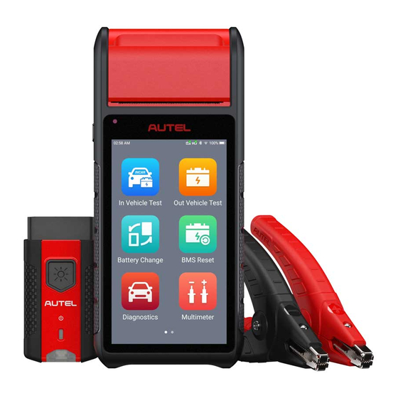
General Introduction MaxiBAS BT608 Touchscreen Battery & Electrical System Analyzer The MaxiBAS BT608 battery and electrical system analyzer is a full-featured battery and starting/charging systems diagnostics tool. The BT608 uses a technology called Adaptive Conductance to more accurately determine the health of battery than traditional battery testers. -
Page 10: Maxibas Bt608 Tester
MaxiBAS BT608 Tester 2.1.1 Function Description Figure 2-1 MaxiBAS BT608 Front/Back/Side View Multimeter Cable Port Battery Clamp Cable Port Micro SD Slot Thermal Printer Paper Exit Power LED — refer to Table 2-1 Power LED Description for details Ambient Light Sensor — detects ambient brightness Lock/Power Button —... -
Page 11: Power Sources
Table 2-1 Power LED Description Color Description Lights solid green when the battery is fully charged. Green Flashes green while charging, and the tester will automatically powers on. Power Lights red when the tester is powered on and the battery level is below 15%. -
Page 12: Technical Specifications
2.1.3 Technical Specifications Item Description Operating System Android 9.0 Screen Display 5.5'' LCD touchscreen with 720x1280 resolution Storage 32 GB Wi-Fi (802.11 a/b/g/n/ac) Connectivity USB 2.0, Type C BT 5.0 + EDR Camera 8 Megapixel Input Voltage 5 V DC Working Current <... -
Page 13: Maxivci V200 - Vehicle Communication Interface (Vci)
2.2 MaxiVCI V200 — Vehicle Communication Interface (VCI) 2.2.1 Function Description Flashlight Power Button Power LED Vehicle/Connection LED Vehicle Data Connector (16-pin) USB Port VCI LED Description Color Description VCI is powered on and performing self- Yellow check. Power LED VCI is ready for use. -
Page 14: Power Sources
2.2.2 Power Sources The VCI device can receive power from following sources: Vehicle Power AC/DC Power Supply Vehicle Power The VCI device operates on 12/24 Volt vehicle power, which is powered by the vehicle data connection port. The device powers on whenever it is connected to an OBD II/EOBD-compliant data link connector (DLC). -
Page 15: Other Accessories
2.3 Other Accessories Battery Clamp Cable Connects tester to battery Battery Side Post Terminal Type S (2pcs) Connects the battery posts and the clamps Battery Side Post Terminal Type T (2pcs) Connects the battery posts and the clamps Power Adapter Together with the USB cable, connects the unit to an external DC power port for power supply. -
Page 16: Getting Started
Getting Started Ensure the unit is sufficiently charged. NOTE The images and illustrations depicted in this manual may differ from the ones in your tool. 3.1 Power Up Press and hold the Lock/Power button on the left side of the tester to switch the unit on. -
Page 17: Page Indicator And System Status Bar
3.1.1 Page Indicator and System Status Bar Descriptions of icons on the status bar and page indicator are displayed below (Table 3-1). Table 3-1 System Status Icons and Page Indicator Icon Name Description Indicates the position of the current page in a list of pages. -
Page 18: Drop-Down Menu
Button Name Description Reads and/or erases trouble codes. See Diagnostics Diagnostics on page 33. Accesses the Multimeter function. (The Multimeter multimeter is sold separately.) See Multimeter on page 40. Accesses system software update menu. Update See Update on page 46. Accesses the VCI Manager, BAS Manager, Settings System Settings Menu, and more. - Page 19 Table 3-3 Drop-down Menu Buttons Button Name Description Settings Quick access to the Settings function. Bluetooth Enables Bluetooth connection. Wi-Fi Enables Wi-Fi connection. Flashlight Turns on/off the flashlight. Screenshot Captures a screenshot of the current screen. Auto Adjusts the screen brightness automatically. Brightness Logger Accesses the Log Collection function.
-
Page 20: Power Off
3.2 Power Off All vehicle communications should be terminated before shutting down the tester. A warning message displays if a shutdown is attempted while the tester is communicating with the vehicle. Forcing a shutdown while the tester is communicating with the vehicle may lead to ECU problems on some vehicles. Please exit the Diagnostics application before shutting down the tester. - Page 21 Connect the red clamp to the positive (+) terminal and the black clamp − to the negative ( ) terminal of the battery.
-
Page 22: In-Vehicle Test
In-vehicle Test In-vehicle Test is used for testing batteries that are installed in a vehicle. An in- vehicle test includes battery test, starter test, and generator test. These tests help determine the health status of the battery, the starter, and the generator. 4.1 Start the Test Select In-vehicle Test on the Home Screen. -
Page 23: Vci Connection
Buttons Table 4-1 Upper Toolbar Buttons Name Button Description Back Returns to the previous screen Home Returns to the Home Screen Displays the battery connection status. The number on the icon indicates the real-time Battery voltage of the tested battery. In the battery test, Connection the button will turn green if the battery is good;... - Page 24 Figure 4-2 Sample VCI Manager Screen Tap the icon to return to the previous screen. The tab will move to the Vehicle information screen. The VCI button on the top right corner of the screen displays a green check mark, indicating the tester is connected to the VCI.
- Page 25 Buttons Name Button Description After the VCI is connected to the device through the vehicle’s OBD Data Link Connector (DLC), AutoVIN turn on the ignition. The vehicle’s VIN number will automatically be recognized. Scan Tap to scan license plate. License Scan VIN Tap to scan Vehicle Identification Number (VIN).
-
Page 26: Battery Test
Tap the icon on the tab to return to the Vehicle information screen. Tap Battery Location on the bottom left corner of the screen and review the battery location diagram. Locate the battery, check the battery information on it, and select the correct battery parameters on the screen. - Page 27 Figure 4-6 Sample Battery Test Result Screen Process Buttons Test Report Function Buttons Process Buttons Tap any of the process buttons to advance to the corresponding test — battery test, starter test or generator test. A status icon will display on the bottom right corner of the button, indicating the test results.
-
Page 28: Starter Test
Function Buttons The Function Buttons at the bottom of the screen vary depending on the operation. Functions include Report and Replace Battery. The table below provides a brief description of the Function Buttons operations: Name Description Tap to view the test data and results in report form. Tap Print on the bottom of the screen to print the test report to the built- Report in thermal printer. -
Page 29: Generator Test
Table 4-3 Starter Test Results Result Description Cranking Normal The starter is good Current Too Low Low momentary discharge capacity Voltage Too Low Low battery storage capacity Not Started The starter is not detected for starting 4.4 Generator Test 15. Follow the on-screen instructions to complete the test. The test results will display as follows: Figure 4-8 Sample Generator Test Result Screen... - Page 30 Table 4-4 Generator Test Results Result Description Charging Normal The generator is good. The belt linking the starter and the generator is loose; Output Too Low The cable linking the starter and battery is loose or corroded. The generator is not properly connected to the ground;...
-
Page 31: Out-Vehicle Test
Out-Vehicle Test Out-vehicle Test is used to test the condition of batteries that are not connected to a vehicle. This function aims to check the health status of the battery only. The compatible battery types and standards are as follows: Types: FLOODED, AGM, AGM SPIRAL, EFB, and GEL Standards: CCA, SAE, CA, EN, EN2, IEC, DIN, JIS, MCA, BCI, and GB 5.1 Test Procedure... -
Page 32: Test Results
Figure 5-2 Sample Out-vehicle Test Results Screen 5.2 Test Results Icons are color-coded to indicate status. Result Description Good Battery Battery meets required standards. Battery is good, but low on charge. Fully charge Good & Recharge the battery. Check for causes of low charge. Battery requires charge to determine its condition. -
Page 33: Battery Replace
Battery Replace The Battery Replace function guides you to replace the battery step by step. The battery replacement process includes Battery Type Suggestion, Preparation, Battery Replacement steps, New Battery Test and Battery Registration. To replace the battery: Tap the Help button at the bottom of each screen to read all the help information carefully before operation, then follow the on-screen instructions to complete the battery replacement. - Page 34 Figure 6-2 Sample New Battery Test Results Screen When the new battery test is completed, tap Next to automatically proceed to Auto Registration in the Battery Reset section.
-
Page 35: Battery Reset
Battery Reset The Battery Reset allows users to access the following functions: Auto registration (after battery replacement), BMS reset, Electric appliance reset, Special function and Battery usage history. Figure 7-1 Sample Battery Reset Main Menu Screen 7.1 Auto Registration (after battery replacement) Auto registration is often used after the successful installation of a new battery, including BMS reset and Electric appliance reset. -
Page 36: Electric Appliance Reset
Figure 7-2 Sample BMS Reset Menu Screen After choosing the desired battery replacement registration, information of Scene, Condition, Influence and Note will display. Click Next to complete registration. 7.1.2 Electric Appliance Reset When the vehicle power is interrupted in order to replace the battery, and a memory saver has not been used, position settings on some vehicle components will be lost. -
Page 37: Special Function
Figure 7-3 Sample Electric Appliance Reset Screen 7.2 Special Function The special function varies by vehicle make. Functions other than battery reset are categorized as special functions. Please follow the on-screen instructions to perform the desired function. Figure 7-4 Sample Reset Closed-circuit Current Monitoring Cycle Screen (BMW vehicles) -
Page 38: Battery Usage History (Only For Bmw Vehicles)
7.3 Battery Usage History (only for BMW vehicles) The Battery usage history function will display the following three tests: SOC (State of Charge) in the last 5 days: monitors the SOC status and diagnoses the health status of the battery. Proportion of SOC duration: displays battery usage habits of drivers. -
Page 39: Diagnostics
Diagnostics The Diagnostics function enables all systems fault detection, and access to live system data for numerous vehicle control systems, such as engine, transmission, and ABS. After choosing a diagnostic type (Automatic selection or Manual selection) on the Diagnostics main menu, there are two options available when accessing the Diagnosis menu: Auto Scan —... - Page 40 Figure 8-1 Sample Auto Scan Operation Screen Progress Percentage — indicates the test progress Main Section Function Buttons Main Section Column 1 — displays the sequence numbers. Column 2 — displays the scanned systems. Column 3 — displays the diagnostic indicators describing test results. The indicators are defined as follows: Fault | #: Fault indicates detection of fault code(s);...
-
Page 41: Control Units
Function Buttons A brief description of the operations of the Auto Scan Function Buttons are displayed in the table below. Table 8-2 Auto Scan Function Buttons Name Description Save Saves the scanning results as a PDF document. Report Displays the diagnostic data in report form. Quick Deletes codes. -
Page 42: Ecu Information
Figure 8-2 Sample Function Menu Screen The Function menu options may vary by vehicle. The Function menu may include: ECU information Read codes Erase codes Live data Freeze frame To perform a diagnostic function: Establish communication with the test vehicle. -
Page 43: Read Codes
Figure 8-3 Sample ECU Information Screen 8.2.2 Read Codes This function retrieves and displays the DTCs from the vehicle’s control system. The Read codes screen varies by each vehicle model being tested. The availability of freeze frame data for viewing varies by vehicle. -
Page 44: Erase Codes
Figure 8-4 Sample Read Codes Screen Main Section Code section — displays the retrieved codes from the vehicle. Description section — describes the retrieved codes in detail. Status section — indicates the status of the retrieved codes. Snowflake icon — indicates freeze frame data is available for viewing. Selecting this icon will display a data screen, which looks and functions similar to the Read codes screen. - Page 45 To erase codes: Tap Erase codes on the Function menu. A message warning that DTCs and/or freeze frame data will be deleted will display: Tap Yes to continue. A confirmation screen will display when the operation is successful. Tap No to exit. Tap ESC on the confirmation screen to exit Erase codes.
-
Page 46: Multimeter
Multimeter The multimeter (sold separately) is a multi-function, multi-range measuring instrument. Connect the multimeter to the BT608 and access its application directly from the home screen to perform AC/DC voltage, AC/DC current, and resistance measurements, and diode, and connectivity tests. The test results will be displayed in number or graph. -
Page 47: Getting Started
the circuit. After current measurement is finished, turn off the power to the circuit before removing the test leads and before reconnecting any disconnected wires or devices. Do not add voltage to the input terminal when measuring resistance. ... -
Page 48: Screen Layout And Operation
Figure 9-1 Sample Multimeter Connection Schematic 9.3 Screen Layout and Operation Tap the Multimeter icon on the main menu to view the multimeter page. -
Page 49: Multimeter Icon
① ② Figure 9-2 Sample Multimeter Test Screen ④ Multimeter icon Digital display Main view section Measurement type selection 9.3.1 Multimeter Icon The Multimeter status icon indicates the connection status with the tester. A green check mark means that the tester and the multimeter are connected; a red “X”... -
Page 50: Measurement Type Selection
9.3.4 Measurement Type Selection This multimeter can be used to measure AC voltage, DC voltage, resistance, AC electricity, DC electricity, diode, and connectivity. The measurement types include: Icon Name Description AC voltage Measures the voltage in the electrical circuit. DC voltage Measures the resistance of the electrical circuit Resistance or the component. - Page 51 Figure 9-3 Sample Schematic Diagram of Current Clamp...
-
Page 52: Update
Update This function allows you to update your BT608 software through Wi-Fi connection, including software for operating system, applications, battery testing, battery registration, and vehicle manufacturers. A notification displays when updates are available. Ensure the tool is connected to a stable Wi-Fi network and follow the on-screen instructions to update software. - Page 53 Upper Toolbar Button Description Returns to the previous page. Tap to acquire all software. Returns to the Home Screen. Search Bar Searches for updates by vehicle manufacturer. Main Section Left Column — displays vehicle logos. Middle Column — displays the newest software version for update and information of the size and release date of the update package.
-
Page 54: Settings
MaxiBAS system. The following options are available in the MaxiBAS settings. Option Description VCI Manager is for connecting the MaxiBAS BT608 with a VCI device via Bluetooth. This option allows you VCI manager to pair the tester with the VCI device, check the communication status, and upgrade the VCI firmware. -
Page 55: Data Manager
Data Manager The Data Manager application allows you to store, print, and review the saved files, manage workshop information and customer information records, and keep test vehicle history records. There are six main functions available. 12.1 Test Records This option stores records of test vehicle history, including battery tests and diagnostics. -
Page 56: Workshop Information
Feedback (submitted), Not Feedback (not submitted but saved) or History (up to the latest 20 test records) data loggings on the diagnostic system. You can edit and send test records by using the Data logging function. Autel support personnel will receive and process submitted reports through the Support... - Page 57 NOTE Thermal Paper The internal printer is shipped with two rolls of thermal paper (2.3’’ wide by 0.98’’ in diameter). Replacement rolls are available in most stationery stores. To replace the paper roll: Open the cover of the printer by gently lifting it upwards. Remove the spent roll if any.
-
Page 58: Remote Desktop
The Remote Desktop application launches the TeamViewer Quick Support program, which is a simple, fast, and secure remote-control interface. You can use the application to receive remote support from Autel's support center, colleagues or friends by allowing them to control your MaxiBAS tester on their PC via the TeamViewer software. - Page 59 To receive remote support from a partner: Power on the BT608. Tap the Remote Desktop application from the MaxiBAS Main Menu. The TeamViewer interface appears and the device ID is generated and shown. Your partner must install the Remote Control software to his/her computer by downloading the TeamViewer program (full version) online (http://www.teamviewer.com).
-
Page 60: Register Tool
Visit http://pro.autel.com. If you already have an Autel account, sign In with your account ID and password; if you are a new member to Autel, click on the Create Autel ID button on the screen to create an ID. The online system will send a verification code to the registered email address. -
Page 61: Maintenance And Service
Maintenance and Service To ensure that the tester and the combined VCI unit perform at their optimum level, we advise that the product maintenance instructions covered in this section are read and followed. 15.1 Maintenance Instructions The following shows how to maintain your devices, together with precautions to take. -
Page 62: Troubleshooting Checklist
Your device may have not been connected to the charger properly. Check the connector. NOTE If the problems persist, please contact Autel technical support personnel or your local distributor. 15.3 About Battery Usage Your tester is powered by a built-in Lithium-ion Polymer battery. This means that, unlike other forms of battery technology, you can recharge your battery while some charge remains without reducing your tester’s autonomy due to the “battery... -
Page 63: Service Procedures
DANGER The built-in Lithium-ion Polymer battery is factory replaceable only; incorrect replacement or tampering with the battery pack may cause an explosion. Do not use a damaged battery charger. Do not disassemble or open, crush, bend or deform, puncture or shred. ... - Page 64 AUTEL NORTH AMERICA Phone: 1-855-AUTEL-US (288-3587) (855-288-3587) Monday-Friday 9am-6pm EST Website: www.autel.com Email: ussupport@autel.com Address: 175 Central Avenue, Suite 200, Farmingdale, New York, USA 11735 AUTEL EUROPE Phone: 0049 (0) 6103-2000520 Monday-Friday, 9:00am-6:00pm Berlin Time ...
-
Page 65: Repair Service
For technical assistance in other markets, please contact your local distributor. 15.4.2 Repair Service If it becomes necessary to return your device for repair, please download the repair service form from www.autel.com, and fill in the form. The following information must be included: Contact name ... -
Page 66: Compliance Information
Compliance Information FCC Compliance FCC ID: WQ8BATSTB2022 WQ8BATSTBV200 This device complies with part 15 of the FCC Rules. Operation is subject to the following two conditions: This device may not cause harmful interference, and This device must accept any interference received, including interference that may cause undesired operation. - Page 67 The radiated output power of this device is below the FCC radio frequency exposure limits. Nevertheless, the device should be used in such a manner that the potential for human contact is minimized during normal operation. The exposure standard for wireless devices employs a unit of measurement known as the Specific Absorption Rate, or SAR.
-
Page 68: Warranty
Warranty Limited One Year Warranty Autel Intelligent Technology Corp., Ltd. (the Company) warrants to the original retail purchaser of this MaxiBAS Battery Tester that should this product or any part thereof during normal usage and under normal conditions be proven defective in material or workmanship and results in product failure... - Page 69 IMPORTANT All contents of the product may be deleted during the process of repair. You should create a back-up copy of any contents of your product before delivering the product for warranty service.
Need help?
Do you have a question about the MaxiBAS BT608 and is the answer not in the manual?
Questions and answers