
Subscribe to Our Youtube Channel
Related Manuals for YOKOGAWA AQ6374


Summary of Contents for YOKOGAWA AQ6374
- Page 1 User’s Manual AQ6374 Optical Spectrum Analyzer Getting Started Guide IM AQ6374-02EN 4th Edition...
- Page 2 Product Registration Thank you for purchasing YOKOGAWA products. YOKOGAWA provides registered users with a variety of information and services. Please allow us to serve you best by completing the product registration form accessible from our website. https://tmi.yokogawa.com/ PIM 103-05E...
- Page 3 For correct operation, please read this manual thoroughly before use. After reading this manual, keep it in a convenient location for quick reference in the event a question arises during operation. There are three manuals for the AQ6374 including this one. Read them along with this manual.
- Page 4 Revisions • 1st Edition: February 2017 • 2nd Edition: October 2017 • 3rd Edition: April 2019 • 4th Edition: April 2021 IM AQ6374-02EN...
-
Page 5: Checking The Contents Of The Package
4 Already attached to the optical input of the AQ6374 front panel. 5 Already attached to the calibration light source output of the AQ6374 front panel. • No. (Instrument Number) Please contact your nearest Yokogawa representative. - Page 6 The English directory in the manual CD contains the PDF files shown below. The CD also contains Japanese manuals. File Name Manual Title Manual No. Features & Operation Manual.pdf AQ6374 Optical Spectrum Analyzer IM AQ6374-01EN User’s Manual Communication Interface.pdf AQ6374 Optical Spectrum Analyzer IM AQ6374-17EN Remote Control User’s Manual...
-
Page 7: Safety Precautions
This manual is an essential part of the product; keep it in a safe place for future reference. Yokogawa Electric Corporation assumes no liability for the customer’s failure to comply with these requirements. - Page 8 Operation in such environments constitutes a safety hazard. • Do Not Remove the Covers or Disassemble or Alter the Instrument Only qualified YOKOGAWA personnel may remove the covers and disassemble or alter the instrument. Opening the cover is dangerous, because some areas inside the instrument have high voltages.
- Page 9 La lumière infrarouge est toujours émise depuis le connecteur de sortie optique. Ne regardez jamais directement dans le connecteur de sortie optique. La lumière infrarouge risquerait de gravement vous blesser ou de provoquer une perte de vision. IM AQ6374-02EN...
- Page 10 Cela pourrait être extrêmement dangereux. • Ne pas retirer le capot, ni démonter ou modifier l’instrument Seul le personnel YOKOGAWA qualifié est habilité à retirer le capot et à démonter ou modifier l’instrument. Certains composants à l’intérieur de l’instrument sont à haute tension et par conséquent, représentent un danger.
- Page 11 21 CFR 1040.10 and 1040.11 except for deviations pursuant to Laser Notice No. 50, dated June 24, 2007. Laser Class 1 Label Information about the Laser Light Source Used Class Laser Type Wavelength Maximum Diameter of Repetation Numerical Output Power Mode Field Rate Aperture EE-LED 1.53µm 0.04mW 9µm IM AQ6374-02EN...
-
Page 12: Regulations And Sales In Various Countries And Regions
Authorized Representative in the EEA Yokogawa Europe B. V. is the authorized representative of Yokogawa Test & Measurement Corporation for this product in the EEA. To contact Yokogawa Europe B. V., see the separate list of worldwide contacts, PIM 113-01Z2. -
Page 13: Symbols And Notation Used In This Manual
Note Calls attention to informmation that is important for proper operation of the instrument. IM AQ6374-02EN... - Page 14 Bold characters used in the procedural explanations indicate characters that are marked on the panel keys or the characters of the soft keys displayed on the screen menu. Unit k: Denotes “1000.” Example: 100kS/s K: Denotes “1024.” Example: 459KB (file data size) IM AQ6374-02EN...
-
Page 15: Flow Of Operation
Flow of Operation The figure below is provided to familarize the first-time user with the general flow of this instrument operation. For a description of each item, see the relevant section or chapter of IM AQ6374-01EN. Preparing for Measurement Alignment Adjustment Section 2.1... -
Page 16: Table Of Contents
Rear Panel ..........................16 Panel Keys and Knobs ......................17 LCD Screen ...........................20 Installing the Instrument ......................22 Attaching the Connector Adapter ...................26 Connecting a Communication Interface .................29 Turning the Power ON/OFF ....................31 Connecting the DUT ......................37 10 Specifications .........................40 External Dimensions ......................43 IM AQ6374-02EN... -
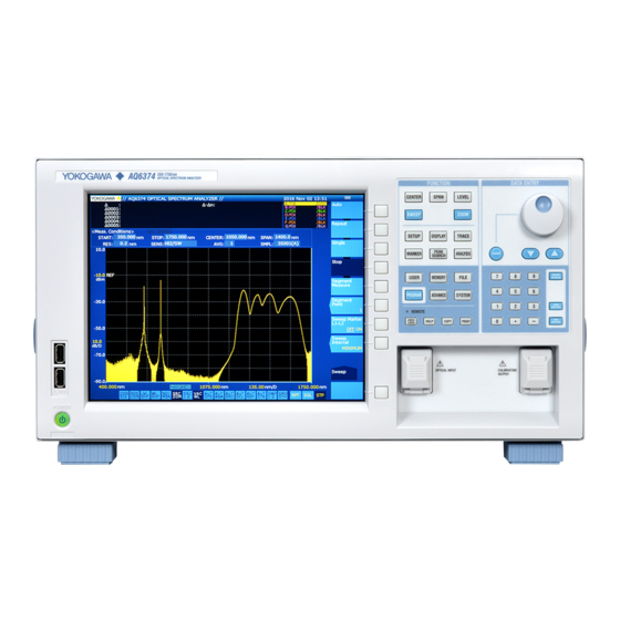
Page 17: Front Panel
Reference light source optical output connector used for alignment adjustments and wavelength calibration. COPY Save the screen as an image file. PRESET Clears all internal settings of the AQ6374 except for the remote interface (ETHERNET, GP-IB, and RS232) settings. IM AQ6374-02EN... -
Page 18: Rear Panel
Analog RGB video signal (SVGA-compliant) interface SERIAL RS-232 interface ETHERNET Ethernet Interface USB interface Used to connect USB storage media or USB mouse Exhaust holes PURGE GAS IN Purge gas filling port PURGE GAS OUT Purge gas outlet port IM AQ6374-02EN... -
Page 19: Panel Keys And Knobs
The TRACE key contains functions related to trace mode settings. MARKER The MARKER key contains functions related to markers. PEAK SEARCH The PEAK SEARCH key contains functions for searching for peaks and bottoms in measured waveforms. ANALYSIS The ANALYSIS key contains functions related to measured waveform analysis. IM AQ6374-02EN... - Page 20 COPY key, the measured waveforms and lists displayed on the screen are output to a file. PRESET The PRESET key clears all internal settings of the AQ6374 except for the remote interface (ETHERNET, GP-IB, and RS232) settings. UNDO/LOCAL The key's function changes depending on the status of the instrument when the UNDO/ LOCAL key is pressed.
- Page 21 (right-most) character is removed, allowing entry of the correct character. By holding the BACK SPACE key down, you can erase the entire entry in the numeric keypad input area and make the numeric keypad input area disappear, returning it to the condition preceding numeric keypad input. IM AQ6374-02EN...
-
Page 22: Lcd Screen
Displays the statuses of main settings (When a setting is ON, its display is depressed, or is displayed with white on black background if the display colors are black and white.) Displays wavelength axis scale per DIV Displays sweep status (RPT=Repeat; SGL=Single; STP=Stop) Displays soft key menu (Displays markers and data analysis results.) IM AQ6374-02EN... - Page 23 4 LCD Screen Parameter display area Parameter input area OVERVIEW display screen (Only displayed when ZOOM function is used.) Displays sub-scale Displayed when SWEEP SPEED is 2x Displays top menu (FUNCTION section) IM AQ6374-02EN...
-
Page 24: Installing The Instrument
La lumière infrarouge est toujours émise depuis le connecteur de sortie optique. Ne regardez jamais directement dans le connecteur de sortie optique. La lumière infrarouge risquerait de gravement vous blesser ou de provoquer une perte de vision. IM AQ6374-02EN... - Page 25 In particular, refrain use under sunlight or light of incandescent light bulbs. In such cases, turn lights around the instrument Off to reduce inaccuracies. IM AQ6374-02EN...
- Page 26 A9088ZM Feet at the rear of the instrument Rack Mounting To rack-mount the instrument, use the separately sold rack mount kit. Product Name Model Rack Mounting Kit for EIA Single 751535-E5 Rack Mounting Kit for JIS Single 751535-E5 IM AQ6374-02EN...
- Page 27 When removing dirt from the case or operation panel, disconnect the power to the circuits under test and the instrument, remove the instrument’s power cord from the power outlet, then wipe gently with a clean, dry cloth. Do not use volatile chemicals since this might cause discoloring and deformation. IM AQ6374-02EN...
-
Page 28: Attaching The Connector Adapter
La lumière infrarouge est toujours émise depuis le connecteur de sortie optique. Ne regardez jamais directement dans le connecteur de sortie optique. La lumière infrarouge risquerait de gravement vous blesser ou de provoquer une perte de vision. IM AQ6374-02EN... - Page 29 On products with the /FC, /SC, /RFC, or /RSC option, connector adapters come attached to the optical input and calibration light source output on the AQ6374 front panel. On products without these options, attach a connector adapter appropriate for the optical connector.
- Page 30 SC type The optical input connector adapter (AQ9447) comes in the following three types. FC type SC type Optical Connectors Types The instrument can use FC or SC type optical connectors. FC type optical SC type optical connector connector IM AQ6374-02EN...
-
Page 31: Connecting A Communication Interface
In addition to a mouse, you can connect a USB storage device. For instructions on using the mouse, see section 3.2 of the User’s Manual, IM AQ6374-01EN. Connecting a Keyboard You can connect a keyboard for entering file names, comments, and other items. Also, the functions and settings of the instrument are assigned to keyboard keys, allowing you to manipulate them with a keyboard just as you would by using the instrument’s panel... - Page 32 Connect the USB storage device to the USB connector on the front panel of the instrument. USB connector Removing See section 7.1 of the User’s Manual, IM AQ6374-01EN. (Using the Remove USB Storage soft key.) CAUTION Do not remove the USB storage device or turn the power OFF while the USB storage device access indicator is blinking.
-
Page 33: Turning The Power On/Off
• N’utilisez pas de rallonge si celle-ci n’est pas reliée à la terre, car la fonction de protection serait compromise. • Si une sortie CA conforme au câble d’alimentation fourni n’est pas disponible et que vous ne pouvez pas relier l’instrument à la terre, ne l’utilisez pas. IM AQ6374-02EN... - Page 34 8 Turning the Power ON/OFF Preparing to Turn ON the Power The AQ6374 has a MAIN POWER switch for turning the main power ON/OFF, and a POWER switch for starting and shutting down the instrument. The POWER switch is a push-button switch;...
- Page 35 CAUTION Do not press the POWER or MAIN POWER switches while initialization is in progress. Doing so can cause malfunction. French ATTENTION N’appuyez pas sur les interrupteurs POWER ou MAIN POWER pendant l’initialisation. Cela pourrait provoquer des dysfonctionnements. IM AQ6374-02EN...
- Page 36 If an error occurs in the memory or some other part of the instrument during initialization, the AQ6374 will stop running with "STEP @ / 9" showing on the screen (where @ is a number between I and 9).
- Page 37 Yes and No soft keys. Press the Yes soft key. The message, “AQ6374 is shutting down. Please wait...” appears, and shut-down begins. If you do not wish to shut down, press the No soft key.
- Page 38 If the shutdown procedure was not performed after the previous session, the following message appears after start up. Failure to properly shut down the instrument can result in damage to the monochromator. When turning OFF the power, always perform the shut down procedure. Press any key to clear this message. IM AQ6374-02EN...
-
Page 39: Connecting The Dut
• Before connecting the input light, make sure that it does not exceed the AQ6374’s maximum rated level. If input light exceeding the maximum rated level is introduced, the optical section may be damaged. - Page 40 • Avant de connecter la lumière d’entrée, vérifiez qu’elle ne dépasse la valeur nominale maximale de l’analyseur AQ6374, car si tel était le cas, la section optique pourrait être endommagée. • Ne pas expirer ou souffler de l’air comprimé dans le monochromateur de l’entrée optique.
- Page 41 Connect the optical connector on the other end of the optical fiber to the optical connector on the DUT. Measuring System AQ6374 Light source Optical fiber Explanation Optical Connectors Types The instrument can use FC or SC type optical connectors. FC type optical connector IM AQ6374-02EN...
-
Page 42: Specifications
100 to 240 VAC, 50/60 Hz, approximately 100 VA External dimensions Approximately 426 (W) x 221 (H) x 459 (D) mm (Note that this excludes the protector and handle) Mass Approximately 19 kg Recommended calibration period 1 year IM AQ6374-02EN... - Page 43 Auto alignment using built-in calibration light source Wavelength Calibration Auto wavelength calibration using built-in calibration light source or an external light source Safety standards Conforming standards EN61010-1 Pollution degree 2 Laser class Class 1 EN60825-1:2014, IEC60825-1:2007, GB7247.1-2012 Environmental standards EU RoHS Directive compliant IM AQ6374-02EN...
- Page 44 Pollution degree 1 applies to closed atmospheres (no pollution, or only dry, non-conductive pollution). Pollution degree 2 applies to normal indoor atmospheres (with only non-conductive pollution). 11: Use a cable of 3 m in length or less. IM AQ6374-02EN...
-
Page 45: External Dimensions
458.8 ( 1.26 ) ( 18.06 ) 12.3 12.3 ( 0.48 ) ( 16.77 ) ( 0.48 ) If not specified, the tolerance is ±3%. However, in cases of less than 10 mm, the tolerance is ±0.3 mm. IM AQ6374-02EN...
Need help?
Do you have a question about the AQ6374 and is the answer not in the manual?
Questions and answers