
Related Manuals for YOKOGAWA AQ6373B


Summary of Contents for YOKOGAWA AQ6373B
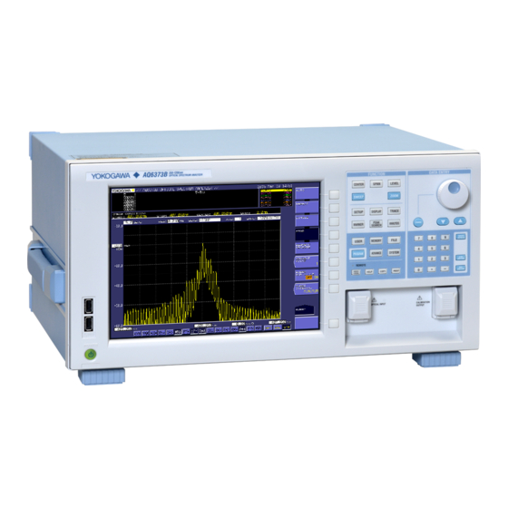
- Page 1 User’s Manual AQ6373B Optical Spectrum Analyzer Getting Started Guide IM AQ6373B-02EN 5th Edition...
- Page 2 Product Registration Thank you for purchasing YOKOGAWA products. YOKOGAWA provides registered users with a variety of information and services. Please allow us to serve you best by completing the product registration form accessible from our homepage. http://tmi.yokogawa.com/ PIM 103-03E...
- Page 3 For correct operation, please read this manual thoroughly before use. After reading this manual, keep it in a convenient location for quick reference in the event a question arises during operation. There are three manuals for the AQ6373B including this one. Read them along with this manual.
- Page 4 Revisions • 1st Edition: March 2015 • 2nd Edition: April 2017 • 3rd Edition: October 2017 • 4th Edition: October 2018 • 5th Edition: April 2019 IM AQ6373B-02EN...
-
Page 5: Checking The Contents Of The Package
Checking the Contents of the Package After opening the package, check the following items before beginning use. If any of the contents are incorrect, missing, or appear to be abnormal, please contact your Yokogawa dealer or representative. AQ6373B Main Unit Check that the model and suffix code on the name plate on the rear of the instrument match those of your order. - Page 6 The English directory in the manual CD contains the PDF files shown below. The CD also contains Japanese manuals. File Name Manual Title Manual No. Features & Operation Manual.pdf AQ6373B Optical Spectrum Analyzer IM AQ6373B-01EN User’s Manual Communication Interface.pdf AQ6370C/AQ6370D/AQ6373/ IM AQ6370C-17EN AQ6373B/AQ6375 Optical Spectrum Analyzer Remote Control User’s Manual...
-
Page 7: Safety Precautions
This manual is an essential part of the product; keep it in a safe place for future reference. Yokogawa Electric Corporation assumes no liability for the customer’s failure to comply with these requirements. - Page 8 Operation in such environments constitutes a safety hazard. • Do Not Remove the Covers or Disassemble or Alter the Instrument Only qualified YOKOGAWA personnel may remove the covers and disassemble or alter the instrument. Opening the cover is dangerous, because some areas inside the instrument have high voltages.
- Page 9 La lumière infrarouge est toujours émise depuis le connecteur de sortie optique. Ne regardez jamais directement dans le connecteur de sortie optique. La lumière infrarouge risquerait de gravement vous blesser ou de provoquer une perte de vision. IM AQ6373B-02EN...
- Page 10 Cela pourrait être extrêmement dangereux. • Ne pas retirer le capot, ni démonter ou modifier l’instrument Seul le personnel YOKOGAWA qualifié est habilité à retirer le capot et à démonter ou modifier l’instrument. Certains composants à l’intérieur de l’instrument sont à haute tension et par conséquent, représentent un danger.
- Page 11 Equipment Classification, Requirements and User’s Guide. In addition, this instrument complies with 21 CFR 1040.10 and 1040.11 except for deviations pursuant to Laser Notice No. 50, dated June 24, 2007. AQ6373B-02, -12 Laser Class 1 Label AQ6373B-01, -10 Laser Class 1 Label...
-
Page 12: Regulations And Sales In Each Country Or Region
With reference to the equipment types in the WEEE directive , this product is classified as a “Monitoring and Control instrumentation” product. When disposing of products in the EU, contact your local Yokogawa Europe B. V. office. Do not dispose in domestic household waste. -
Page 13: Conventions Used In This Manual
Note Calls attention to information that is important for proper operation of the instrument. IM AQ6373B-02EN... - Page 14 Bold characters used in the procedural explanations indicate characters that are marked on the panel keys or the characters of the soft keys displayed on the screen menu. Unit k: Denotes “1000.” Example: 100kS/s K: Denotes “1024.” Example: 459KB (file data size) IM AQ6373B-02EN...
-
Page 15: Flow Of Operation
For a description of each item, see the relevant section or chapter of IM AQ6373B-01EN. Preparing for Measurement Installing the Instrument Chapter 5 in IM AQ6373B-02EN Turning the Power ON/OFF Chapter 7 in IM AQ6373B-02EN Alignment Adjustment Section 2.1... -
Page 16: Table Of Contents
Flow of Operation ......................... xiii Front Panel ..........................1 Rear Panel ..........................2 Panel Keys and Knobs ......................3 LCD Screen ..........................6 Installing the Instrument ......................8 Connecting a Communication Interface .................12 Turning the Power ON/OFF ....................14 Connecting the DUT ......................20 Specifications .........................24 External Dimensions ......................27 IM AQ6373B-02EN... -
Page 17: Front Panel
(when the built-in light source specification is -L1) COPY Save the screen as an image file. PRESET Clears all internal settings of the AQ6373B except for the remote interface (ETHERNET, GP-IB, and RS232) settings. IM AQ6373B-02EN... -
Page 18: Rear Panel
Rear Panel Rear Panel AQ6373B-02, -12 AQ6373B-01, -10 2 3 4 2 3 4 Name Function GP-IB GP-IB port for controlling this unit through an external computer TRIGGER IN Input connector for synchronous signals for the synchronous measurement function with the Tunable Laser... -
Page 19: Panel Keys And Knobs
The TRACE key contains functions related to trace mode settings. MARKER The MARKER key contains functions related to markers. PEAK SEARCH The PEAK SEARCH key contains functions for searching for peaks and bottoms in measured waveforms. ANALYSIS The ANALYSIS key contains functions related to measured waveform analysis. IM AQ6373B-02EN... - Page 20 When you press the COPY key, the measured waveforms and lists displayed on the screen are output to the internal printer or a file. PRESET The PRESET key clears all internal settings of the AQ6373B except for the remote interface (ETHERNET, GP-IB, and RS232) settings. UNDO/LOCAL The key's function changes depending on the status of the instrument when the UNDO/ LOCAL key is pressed.
- Page 21 (right-most) character is removed, allowing entry of the correct character. By holding the BACK SPACE key down, you can erase the entire entry in the numeric keypad input area and make the numeric keypad input area disappear, returning it to the condition preceding numeric keypad input. IM AQ6373B-02EN...
-
Page 22: Lcd Screen
Displays the statuses of main settings (When a setting is ON, its display is depressed, or is displayed with white on black background if the display colors are black and white.) Displays wavelength axis scale per DIV Displays sweep status (RPT=Repeat; SGL=Single; STP=Stop) Displays soft key menu (Displays markers and data analysis results.) IM AQ6373B-02EN... - Page 23 4 LCD Screen Parameter display area Parameter input area OVERVIEW display screen (Only displayed when ZOOM function is used.) Displays sub-scale Displayed when SWEEP SPEED is 2x IM AQ6373B-02EN...
-
Page 24: Installing The Instrument
La lumière infrarouge est toujours émise depuis le connecteur de sortie optique. Ne regardez jamais directement dans le connecteur de sortie optique. La lumière infrarouge risquerait de gravement vous blesser ou de provoquer une perte de vision. IM AQ6373B-02EN... - Page 25 There are inlet holes on the both 20 cm or sides of the instrument. more 20 cm or 20 cm or more more 20 cm or more Also be sure to maintain sufficient clearance for connecting measurement cables. IM AQ6373B-02EN...
- Page 26 Remove the four seals the rack mount attachment holes on each side of the instrument near the front. Place seals over the feet and handle attachment holes. Attach the rack mount kit to the instrument. Mount the instrument on a rack. IM AQ6373B-02EN...
- Page 27 This instrument complies with the EMC standard under specific operating environment and operating conditions. If the installation, wiring, and so on are not appropriate, the compliance conditions of the EMC standard may not be met. In such cases, the user will be required to take appropriate measures. IM AQ6373B-02EN...
-
Page 28: Connecting A Communication Interface
• In addition to a USB keyboard, the USB interfaces can be used to connect USB storage and a USB mouse. For information on operations using the keyboard, see section 4.2 of the User’s Manual IM AQ6373B-01EN. IM AQ6373B-02EN... - Page 29 Connect the USB storage device to the USB connector on the front panel of the instrument. USB connector Removing See section 8.1 of the User’s Manual IM AQ6373B-01EN. (Using the REMOVE USB STORAGE soft key.) CAUTION Do not remove the USB storage device or turn the power OFF while the USB storage device access indicator is blinking.
-
Page 30: Turning The Power On/Off
• N’utilisez pas de rallonge si celle-ci n’est pas reliée à la terre, car la fonction de protection serait compromise. • Si une sortie CA conforme au câble d’alimentation fourni n’est pas disponible et que vous ne pouvez pas relier l’instrument à la terre, ne l’utilisez pas. IM AQ6373B-02EN... - Page 31 7 Turning the Power ON/OFF Preparing to Turn ON the Power The AQ6373B has a MAIN POWER switch for turning the main power ON/OFF, and a POWER switch for starting and shutting down the instrument. The POWER switch is a push-button switch;...
- Page 32 Turn ON the MAIN POWER switch on the rear panel of the instrument. The POWER switch on the front panel of the instrument lights orange. AQ6373B-02, -12 AQ6373B-01, -10 Press the POWER switch on the front panel of the instrument. The color of the switch turns from orange to green.
- Page 33 Perform the alignment adjustment after a one-hour warm-up. See section 3.5 of the User’s Manual, IM AQ6373B-01EN for details on the alignment adjustment operation, and 3.6 for wavelength calibration. When the Power-on Operation Does Not Finish Normally Turn off the power switch, and check that : •...
- Page 34 YES and NO soft keys. Press the YES soft key. The message, “AQ6373B is shutting down. Please wait...” appears, and shut-down begins. If you do not wish to shut down, press the NO soft key.
- Page 35 If you do not perform a shutdown procedure, the monochromator will not be retracted. Transporting or moving the instrument repeatedly in this condition may damage the monochromator. When turning OFF the power, always perform the shut down procedure. Press any key to clear this message. IM AQ6373B-02EN...
-
Page 36: Connecting The Dut
• Before connecting the input light, make sure that it does not exceed the AQ6373B’s maximum rated level. If input light exceeding the maximum rated level is introduced, the optical section may be damaged. - Page 37 • Avant de connecter la lumière d’entrée, vérifiez qu’elle ne dépasse la valeur nominale maximale de l’analyseur AQ6373B, car si tel était le cas, la section optique pourrait être endommagée. • Appuyez fermement le connecteur optique sur la surface nettoyante du nettoyeur.
- Page 38 Press the FIBER CORE SIZE soft key. Pressing the key repeatedly toggles between SMALL and LARGE. If the core diameter of the fiber under test is 100 µm or less, choose SMALL. If larger than 100 µm, choose LARGE. IM AQ6373B-02EN...
- Page 39 Connect the optical connector on the other end of the optical fiber to the optical connector on the DUT. Measuring System AQ6373B Light source Optical fiber Explanation Optical Connectors Types The instrument can use FC (PC) type optical connectors. FC type optical connector IM AQ6373B-02EN...
-
Page 40: Specifications
Specifications For the specifications of the limited model (SUFFIX -02, -01), see IM AQ6373B-51EN, a manual specifically for the limited model (SUFFIX -02, -01). Item Specifications Applicable fiber SM, GI (50/125 μm, 62.5/125 μm), Large core size fibers (core diameter of up to 800 µm) Measurement wavelength range 350 to 1200 nm Span 0.5 nm to 850 nm (entire wavelength range), 0 nm... - Page 41 • Use a VIDEO OUT connector and a D-sub 15pin VGA shielded cable • Use a USB peripheral (such as a mouse) that uses a USB port and shielded cable • Use the GP-IB interface connector and a GP-IB shielded cable IM AQ6373B-02EN...
- Page 42 10: Use a cable of 3 m in length or less. 11: Use a cable of 30 m in length or less. 12: Use USB peripherals complying with EMC. *: Typical values(typ.) are typical or mean values. They are not strictly guaranteed. IM AQ6373B-02EN...
-
Page 43: External Dimensions
External Dimensions Unit : mm (approx. inch) AQ6373B-02, -12 AQ6373B-01, -10 REAR VIEW ( 0.58 ) 14.8 458.8 ( 18.06 ) ( 1.26 ) 12.3 12.3 ( 0.48 ) ( 16.77 ) ( 0.48 ) If not specified, the tolerance is ±3%. However, in cases of less than 10 mm, the tolerance is ±0.3 mm.
Need help?
Do you have a question about the AQ6373B and is the answer not in the manual?
Questions and answers