Table of Contents
Advertisement
Available languages
Available languages
Quick Links
Quick Start
Thank you for purchasing the MSI®
MAG B560M BAZOOKA
motherboard. This Quick Start section provides demonstration
diagrams about how to install your computer. Some of the
installations also provide video demonstrations. Please link to the
URL to watch it with the web browser on your phone or tablet. You
may have even link to the URL by scanning the QR code.
Kurzanleitung
Danke, dass Sie das MSI®
MAG B560M BAZOOKA
Motherboard
gewählt haben. Dieser Abschnitt der Kurzanleitung bietet eine Demo
zur Installation Ihres Computers. Manche Installationen bieten
auch die Videodemonstrationen. Klicken Sie auf die URL, um diese
Videoanleitung mit Ihrem Browser auf Ihrem Handy oder Table
anzusehen. Oder scannen Sie auch den QR Code mit Ihrem Handy,
um die URL zu öffnen.
Présentation rapide
Merci d'avoir choisi la carte mère MSI®
MAG B560M
BAZOOKA.
Ce manuel fournit une rapide présentation avec des illustrations
explicatives qui vous aideront à assembler votre ordinateur. Des
tutoriels vidéo sont disponibles pour certaines étapes. Cliquez sur
le lien fourni pour regarder la vidéo sur votre téléphone ou votre
tablette. Vous pouvez également accéder au lien en scannant le QR
code qui lui est associé.
Быстрый старт
Благодарим вас за покупку материнской платы MSI®
MAG B560M
BAZOOKA. В этом разделе представлена информация, которая
поможет вам при сборке комьютера. Для некоторых этапов сборки
имеются видеоинструкции. Для просмотра видео, необходимо
открыть соответствующую ссылку в веб-браузере на вашем
телефоне или планшете. Вы также можете выполнить переход по
ссылке, путем сканирования QR-кода.
I
Quick Start
Advertisement
Chapters
Table of Contents

Related Manuals for MSI MAG B560M BAZOOKA


Summary of Contents for MSI MAG B560M BAZOOKA
- Page 1 Videoanleitung mit Ihrem Browser auf Ihrem Handy oder Table anzusehen. Oder scannen Sie auch den QR Code mit Ihrem Handy, um die URL zu öffnen. Présentation rapide Merci d’avoir choisi la carte mère MSI® MAG B560M BAZOOKA. Ce manuel fournit une rapide présentation avec des illustrations explicatives qui vous aideront à...
- Page 2 Installing a Processor/ Installation des Prozessors/ Installer un processeur/ Установка процессора Youtube ⚽ https://youtu.be/Xv89nhFk1vc Quick Start...
- Page 3 Installing DDR4 memory/ Installation des DDR4-Speichers/ Installer une mémoire DDR4/ Установка памяти DDR4 Youtube ⚽ http://youtu.be/T03aDrJPyQs DIMMA1 DIMMA2 DIMMA2 DIMMA2 DIMMB1 DIMMB2 DIMMB2 Quick Start...
- Page 4 Connecting the Front Panel Header/ Anschließen der Frontpanel-Stiftleiste/ Connecter un connecteur du panneau avant/ Подключение разъемов передней панели Youtube ⚽ http://youtu.be/DPELIdVNZUI Power LED Power Switch JFP1 Reserved HDD LED Reset Switch HDD LED + Power LED + HDD LED - Power LED - Reset Switch Power Switch...
- Page 5 Installing the Motherboard/ Installation des Motherboards/ Installer la carte mère/ Установка материнской платы ⚽ https://youtu.be/wWI6Qt51Wnc Torque: 3 kgf·cm* BAT1 *3 kgf·cm = 0.3 N·m = 2.6 lbf·in Quick Start...
- Page 6 Connecting the Power Connectors/ Stromanschlüsse anschliessen/ Connecter les câbles du module d’alimentation/ Подключение разъемов питания Youtube ⚽ http://youtu.be/gkDYyR_83I4 ATX_PWR1 CPU_PWR1 Quick Start...
- Page 7 Installing SATA Drives/ Installation der SATA-Laufwerke/ Installer le disque dur SATA/ Установка дисков SATA Youtube ⚽ http://youtu.be/RZsMpqxythc Quick Start...
- Page 8 Installing a Graphics Card/ Einbau der Grafikkarte/ Installer une carte graphique/ Установка дискретной видеокарты Youtube ⚽ http://youtu.be/mG0GZpr9w_A VIII Quick Start...
- Page 9 Connecting Peripheral Devices/ Peripheriegeräte/ Connecter un périphérique anschliessen/ Подключение периферийных устройств Quick Start...
- Page 10 Power On/ Einschalten/ Mettre sous-tension/ Включение питания Quick Start...
-
Page 11: Table Of Contents
JDASH1 : Tuning Controller connector ..............23 EZ Debug LED ....................... 23 JRGB1: RGB LED connector ................. 24 JRAINBOW1: Addressable RGB LED connector ..........25 Installing OS, Drivers & MSI Center ..............26 Installing Windows® 10 ..................26 Installing Drivers ....................26 MSI Center ......................26 UEFI BIOS ...................... -
Page 12: Safety Information
Safety Information ∙ The components included in this package are prone to damage from electrostatic discharge (ESD). Please adhere to the following instructions to ensure successful computer assembly. ∙ Ensure that all components are securely connected. Loose connections may cause the computer to not recognize a component or fail to start. -
Page 13: Case Stand-Off Notification
Case stand-off notification Before installing the motherboard into the case, install first the necessary mounting stand-off required for a motherboard on the mounting plate in the case. To prevent damage to the motherboard, any unnecessary mounting stand-off between the motherboard circuits and the computer case is prohibited. The Case standoff keep out zone signs will be marked on the backside of motherboard (as shown below) to serve as a warning to user. -
Page 14: Specifications
∙ Supports Dual-Channel mode ∙ Supports non-ECC mode, un-buffered memory ∙ Supports Intel® Extreme Memory Profile (XMP) * Please refer www.msi.com for more information on compatible memory. ∙ 1x PCIe x16 slot ▪ PCI_E1 (From CPU) ▫ Supports up to PCIe 4.0 for 11th Gen Intel® CPU Expansion Slot ▫... - Page 15 * SATA2 will be unavailable when installing M.2 SATA SSD in the M2_1 slot. ** Before using Intel® Optane™ memory modules, please ensure that you have updated the drivers and BIOS to the latest version from MSI website. Intel® B560 Chipset ▪...
- Page 16 Continued from previous page ∙ 1x 24-pin ATX main power connector ∙ 1x 8-pin ATX 12V power connector ∙ 6x SATA 6Gb/s connectors ∙ 2x M.2 slots (M-Key) ∙ 1x USB 3.2 Gen 1 5Gbps connector (supports additional 2 USB 3.2 Gen 1 ports) ∙...
- Page 17 ∙ ACPI 6.2, SMBIOS 3.0 ∙ Multi-language ∙ Drivers ∙ MSI Center ∙ Intel® Extreme Tuning Utility ∙ MSI APP Player (BlueStacks) Software ∙ Open Broadcaster Software (OBS) ∙ CPU-Z MSI GAMING ∙ Google Chrome™, Google Toolbar, Google Drive ∙ Norton™ Internet Security Solution ∙...
- Page 18 Continued from previous page ∙ Audio ▪ Audio Boost ∙ Cooling ▪ M.2 Shield Frozr ▪ Pump Fan ▪ Smart Fan Control ∙ LED ▪ Mystic Light Extension (RAINBOW/RGB) ▪ EZ DEBUG LED Special Features ∙ Performance ▪ DDR4 Boost ▪...
-
Page 19: Package Contents
Package contents Please check the contents of your motherboard package. It should contain: Motherboard MAG B560M BAZOOKA User manual Documentation Quick installation guide Application Driver DVD Cable SATA 6G cables (2 cables/pack) M.2 screw + standoff (2 sets/pack) IO shielding... -
Page 20: Rear I/O Panel
Rear I/O Panel Line-in 2.5 Gbps LAN PS/2 Combo port DisplayPort Mic-in USB 3.2 Gen 2 USB 2.0 Type-A Line-out (10Gbps) Type-A USB 3.2 Gen 1 (5Gbps) Type-A LAN Port LED Status Table Link/ Activity LED Speed LED Status Description Status Description No link... - Page 21 ∙ Device Selection - allows you to select a audio output source to change the related options. The check sign indicates the devices as default. ∙ Application Enhancement - the array of options will provide you a complete guidance of anticipated sound effect for both output and input device. ∙...
-
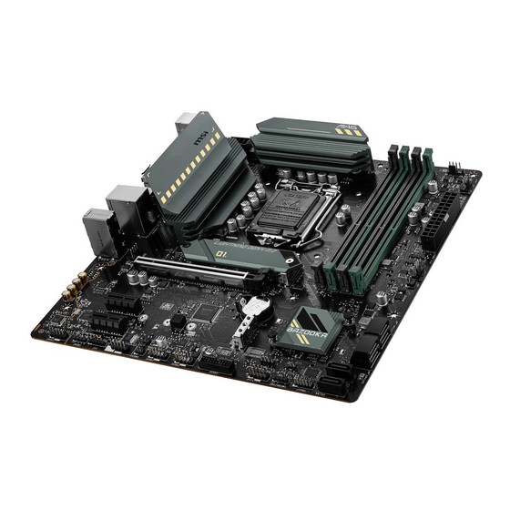
Page 22: Overview Of Components
Overview of Components Processor Socket DIMMA1 DIMMA2 CPU_PWR1 DIMMB1 DIMMB2 CPU_FAN1 PUMP_FAN1 ATX_PWR1 SYS_FAN1 SYS_FAN2 M2_1 PCI_E1 JCI1 SATA▼1▲2 BAT1 PCI_E2 SATA▼3▲4 M2_2 PCI_E3 SATA5 JAUD1 SATA6 JRGB1 JTPM1 JBAT1 JRAINBOW1 JCOM1 JFP1 JDASH1 JFP2 JUSB1 JUSB3 JUSB2 Overview of Components... -
Page 23: Cpu Socket
Always unplug the power cord from the power outlet before installing or removing ∙ the CPU. Please retain the CPU protective cap after installing the processor. MSI will deal ∙ with Return Merchandise Authorization (RMA) requests if only the motherboard comes with the protective cap on the CPU socket. -
Page 24: Dimm Slots
It is recommended to use a more efficient memory cooling system for full DIMMs ∙ installation or overclocking. ∙ The stability and compatibility of installed memory module depend on installed CPU and devices when overclocking. Please refer www.msi.com for more information on compatible memory. ∙ Overview of Components... -
Page 25: Pci_E1~3: Pcie Expansion Slots
PCI_E3: PCIe 3.0 x1 (From B560 chipset) ⚠ Important If you install a large and heavy graphics card, you need to use a tool such as MSI ∙ Gaming Series Graphics Card Bolster to support its weight to prevent deformation of the slot. -
Page 26: M2_1~2: M.2 Slots (Key M)
M2_1~2: M.2 Slots (Key M) ⚽ Video Demonstration Watch the video to learn how to Install M.2 SSD. https://youtu.be/2UeWMgjwogU M2_1 M2_2 ⚠ Important Intel® RST only supports PCIe M.2 SSD with UEFI ROM. ∙ Intel® Optane™ Memory Ready for M2_2 slot. ∙... - Page 27 3. Secure the supplied M.2 standoff according to your M.2 SSD length if need. 4. Insert your M.2 SSD into the M.2 slot at a 30-degree angle. 5. Secure the M.2 SSD in place with the supplied M.2 8.5H screw. ⚠...
-
Page 28: Jfp1, Jfp2: Front Panel Connectors
JFP1, JFP2: Front Panel Connectors These connectors connect to the switches and LEDs on the front panel. Buzzer JFP2 Speaker Speaker - Buzzer + Buzzer - Speaker + Power LED Power Switch JFP1 Reserved HDD LED Reset Switch HDD LED + Power LED + HDD LED - Power LED -... -
Page 29: Cpu_Pwr1, Atx_Pwr1: Power Connectors
CPU_PWR1, ATX_PWR1: Power Connectors These connectors allow you to connect an ATX power supply. CPU_PWR1 Ground +12V Ground +12V Ground +12V Ground +12V +3.3V +3.3V +3.3V -12V Ground Ground PS-ON# Ground Ground Ground ATX_PWR1 Ground Ground PWR OK 5VSB +12V +12V +3.3V Ground... -
Page 30: Jusb3: Usb 3.2 Gen 1 Connector
No Pin ⚠ Important Note that the VCC and Ground pins must be connected correctly to avoid possible ∙ damage. In order to recharge your iPad,iPhone and iPod through USB ports, please install ∙ MSI® Center utility. Overview of Components... -
Page 31: Cpu_Fan1, Pump_Fan1, Sys_Fan1~2: Fan Connectors
CPU_FAN1, PUMP_FAN1, SYS_FAN1~2: Fan Connectors Fan connectors can be classified as PWM (Pulse Width Modulation) Mode or DC Mode. PWM Mode fan connectors provide constant 12V output and adjust fan speed with speed control signal. DC Mode fan connectors control fan speed by changing voltage. However, you can follow the instruction below to adjust the fan connector to PWM or DC Mode manually. -
Page 32: Jci1: Chassis Intrusion Connector
JCI1: Chassis Intrusion Connector This connector allows you to connect the chassis intrusion switch cable. Normal Trigger the chassis (default) intrusion event Using chassis intrusion detector 1. Connect the JCI1 connector to the chassis intrusion switch/ sensor on the chassis. 2. -
Page 33: Jbat1: Clear Cmos (Reset Bios) Jumper
JBAT1: Clear CMOS (Reset BIOS) Jumper There is CMOS memory onboard that is external powered from a battery located on the motherboard to save system configuration data. If you want to clear the system configuration, set the jumpers to clear the CMOS memory. Keep Data Clear CMOS/ (default) -
Page 34: Jrgb1: Rgb Led Connector
(12V/G/R/B) with the maximum power rating of 3A (12V). ∙ Always turn off the power supply and unplug the power cord from the power outlet before installing or removing the RGB LED strip. ∙ Please use MSI’s software to control the extended LED strip. Overview of Components... -
Page 35: Jrainbow1: Addressable Rgb Led Connector
(5V). In the case of 20% brightness, the connector supports up to 200 LEDs. Always turn off the power supply and unplug the power cord from the power outlet ∙ before installing or removing the RGB LED strip. ∙ Please use MSI’s software to control the extended LED strip. Overview of Components... -
Page 36: Installing Os, Drivers & Msi Center
MSI Center is an application that helps you easily optimize game settings and smoothly use content creation softwares. It also allows you to control and synchronize LED light effects on PCs and other MSI products. With MSI Center, you can customize ideal modes, monitor system performance, and adjust fan speed. -
Page 37: Uefi Bios
UEFI has many new functions and advantages that traditional BIOS cannot achieve, and it will completely replace BIOS in the future. The MSI UEFI BIOS uses UEFI as the default boot mode to take full advantage of the new chipset’s capabilities. -
Page 38: Bios Setup
* When you press F10, a confirmation window appears and it provides the modification information. Select between Yes or No to confirm your choice. BIOS User Guide If you’d like to know more instructions on setting up the BIOS, please refer to http://download.msi.com/manual/mb/Intel500BIOS.pdf or scan the QR code to access. UEFI BIOS... -
Page 39: Resetting Bios
Updating BIOS Updating BIOS with M-FLASH Before updating: Please download the latest BIOS file that matches your motherboard model from MSI website. And then save the BIOS file into the USB flash drive. Updating BIOS: 1. Insert the USB flash drive that contains the update file into the USB port. - Page 40 ∙ Please close all other application software before updating the BIOS. To update BIOS: 1. Install and launch MSI Center and go to Support page. 2. Select Live Update and click on Advance button. 3. Select the BIOS file and click on Install button.
- Page 41 JDASH1 : Tuning Controller-Anschluss ............... 23 EZ Debug LED ....................... 23 JRGB1: RGB LED Anschluss ................24 JRAINBOW1: Adressierbare RGB LED Anschluss ..........25 Installation von OS, Treibern & MSI Center ............26 Installation von Windows 10 ................26 ®...
-
Page 42: Sicherheitshinweis
Sicherheitshinweis ∙ Die im Paket enthaltene Komponenten sind der Beschädigung durch elektrostatischen Entladung (ESD). Beachten Sie bitte die folgenden Hinweise, um die erfolgreichen Computermontage sicherzustellen. ∙ Stellen Sie sicher, dass alle Komponenten fest angeschlossen sind. Lockere Steckverbindungen können Probleme verursachen, zum Beispiel: Der Computer erkennt eine Komponente nicht oder startet nicht. -
Page 43: Hinweise Zum Gehäuseabstandshalter
Hinweise zum Gehäuseabstandshalter Installieren Sie vor dem Einbau des Motherboards in das Gehäuse zunächst den für ein Motherboard erforderlichen Abstandshalter auf der Montageplatte im Gehäuse. Um eine Beschädigung des Motherboards zu vermeiden, sind unnötige Abstandshalter zwischen den Motherboard-Schaltkreisen und dem Computergehäuse verboten. Die Schilder „Case Standoff Keep Out Zone (Gehäuseabstandszone freihalten )“... -
Page 44: Spezifikationen
∙ Unterstützt non-ECC, ungepufferte Speicher ∙ Unterstützt Intel® Extreme Memory Profile (XMP) * Weitere Informationen zu kompatiblen Speicher finden Sie unter: http://www.msi.com. ∙ 1x PCIe x16 Steckplatz ▪ PCI_E1 (von CPU) ▫ Unterstützt bis zu PCIe 4.0 für 11. Gen Intel® CPU Erweiterung- anschlüsse... - Page 45 * SATA2 wird nicht zur Verfügung stehen, wenn Sie eine M.2 SATA SSD im M2_1 Steckplatz installieren. ** Bevor Sie Intel® Optane™ Speichermodule verwenden, stellen Sie bitte über Downloads von der MSI Website sicher, dass die Treiber und das BIOS auf dem neuesten Stand sind. Intel® B560 Chipsatz ▪...
- Page 46 Fortsetzung der vorherigen Seite ∙ 1x 24-poliger ATX Stromanschluss ∙ 1x 8-poliger ATX 12V Stromanschluss ∙ 6x SATA 6Gb/s Anschlüsse ∙ 2x M.2 Steckplätze (M-Key) ∙ 1x USB 3.2 Gen 1 5Gbit/s Anschluss (unterstützt zusätzliche 2 USB 3.2 Gen 1 Anschlüsse) ∙...
- Page 47 ∙ ACPI 6.2, SMBIOS 3.0 ∙ Mehrsprachenunterstützung ∙ Treiber ∙ MSI Center ∙ Intel® Extreme Tuning Utility ∙ MSI APP Player (BlueStacks) Software ∙ Open Broadcaster Software (OBS) ∙ CPU-Z MSI GAMING ∙ Google Chrome™, Google Toolbar, Google Drive ∙ Norton™ Internet Security Solution ∙...
- Page 48 Fortsetzung der vorherigen Seite ∙ Audio ▪ Audio Boost ∙ Kühlung ▪ M.2 Shield Frozr ▪ Pump-Lüfter ▪ Smart-Lüftersteuerung ∙ LED ▪ Mystic Light Extension (RAINBOW/RGB) ▪ EZ DEBUG LED Besondere ∙ Leistung Funktionen ▪ DDR4 Boost ▪ Core Boost ▪...
-
Page 49: Packungsinhalt
Packungsinhalt Überprüfen Sie den Packungsinhalt des Mainboards. Die Packung sollte enthalten: Motherboard MAG B560M BAZOOKA Benutzerhandbuch Dokumentation Schnellinstallationsanleitung Anwendung Treiber DVD Kabel SATA 6G Kabel (2 Kabel pro Packung) M.2 Schraube + Abstand (2 Stück pro Packung) Anschlussblende Zubehör Dragon-Aufkleber... -
Page 50: Rückseite E/A
Rückseite E/A Line-In 2,5 Gbit/s LAN PS/2 Combo-Anschluss DisplayPort Mic-In USB 3.2 Gen 2 USB 2.0 Typ-A Line-Out (10Gbit/s) Typ-A USB 3.2 Gen 1 (5Gbit/s) Typ-A LAN Port LED Zustandstabelle Verbindung/ Aktivität LED Geschwindigkeit LED Zustand Bezeichnung Zustand Bezeichnung Keine Verbindung 10 Mbit/s Verbindung Gelb Verbindung... - Page 51 ∙ Geräteauswahl - Ermöglicht die Auswahl der Audio-Ausgangs Quelle. Das aktuell aktivierte Gerät ist mit einem Haken gekennzeichnet. ∙ Optimierungen - Die Vielfalt an Optionen bietet eine komplette Anleitung von erwarteten Sound-Effekt für beide Ausgangs- und Eingangsvorrichtung. ∙ Lautstärke - Steuert die Lautstärke und die Balance-Einstellung der Lautsprecher, die im Front-Panel oder auf der Rückseite des PCs eingesteckt sind.
-
Page 52: Übersicht Der Komponenten
Übersicht der Komponenten Prozessorsockel DIMMA1 DIMMA2 CPU_PWR1 DIMMB1 DIMMB2 CPU_FAN1 PUMP_FAN1 ATX_PWR1 SYS_FAN1 SYS_FAN2 M2_1 PCI_E1 JCI1 SATA▼1▲2 BAT1 PCI_E2 SATA▼3▲4 M2_2 PCI_E3 SATA5 JAUD1 SATA6 JRGB1 JTPM1 JBAT1 JRAINBOW1 JCOM1 JFP1 JDASH1 JFP2 JUSB1 JUSB3 JUSB2 Übersicht der Komponenten... -
Page 53: Cpu Sockel
Sie jedoch bitte sicher, dass die betroffenen Komponenten mit den abweichenden Einstellungen während des Übertaktens zurecht kommen. Von jedem Versuch des Betriebes außerhalb der Produktspezifikationen kann nur abgeraten werden. MSI übernehmt keinerlei Garantie für die Schäden und Risiken, die aus einem unzulässigem Betrieb oder einem Betrieb außerhalb der Produktspezifikation resultieren. -
Page 54: Dimm Steckplätze
DIMMs oder beim Übertakten zu verwenden. Die Stabilität und Kompatibilität beim Übertakten der installierten Speichermodule ∙ sind abhängig von der installierten CPU und den installierten Geräten. ∙ Weitere Informationen zu kompatiblen Speichermodulen finden Sie unter: http://www.msi.com. Übersicht der Komponenten... -
Page 55: Pci_E1~3: Pcie Erweiterungssteckplätze
PCI_E1~3: PCIe Erweiterungssteckplätze PCI_E1: PCIe 4.0 x16 (von CPU) BAT1 PCI_E2: PCIe 3.0 x1 (von B560 Chipsatz) PCI_E3: PCIe 3.0 x1 (von B560 Chipsatz) ⚠ Wichtig Wenn Sie eine große und schwere Grafikkarte einbauen, benötigen Sie einen ∙ Grafikkarten-Stabilisator (Graphics Card Bolster) der das Gewicht trägt und eine Verformung des Steckplatzes vermeidet. -
Page 56: M2_1~2: M.2 Steckplätze (Key M)
M2_1~2: M.2 Steckplätze (Key M) ⚽ Video-Demonstration Eine anschauliche Darstellung zur Installation einesr M.2 SSD finden Sie im Video. https://youtu.be/2UeWMgjwogU M2_1 M2_2 ⚠ Wichtig Intel RST unterstützt nur PCIe M.2 SSD mit UEFI ROM. ∙ ® Intel Optane Technik unterstützt M2_3-Steckplatz. ∙... - Page 57 3. Wählen Sie die Montageposition entsprechend Ihrer M.2 SSD Länge. 4. Stecken Sie eine M.2-SSD im 30-Grad-Winkel in den M.2-Steckplatz. 5. Schrauben Sie den M.2 SSD mit 8,5H M.2-Schraube. ⚠ Wichtig Überspringen Sie Schritt 3 und Schritt 5, wenn Sie eine 2280 M.2 in den M2_1- Steckplatz installieren.
-
Page 58: Jfp1, Jfp2: Frontpanel-Anschlüsse
JFP1, JFP2: Frontpanel-Anschlüsse Diese Anschlüsse verbinden die Schalter und LEDs des Frontpanels. Buzzer JFP2 Speaker Speaker - Buzzer + Buzzer - Speaker + Power LED Power Switch JFP1 Reserved HDD LED Reset Switch HDD LED + Power LED + HDD LED - Power LED - Reset Switch Power Switch... -
Page 59: Cpu_Pwr1, Atx_Pwr1: Stromanschlüsse
CPU_PWR1, ATX_PWR1: Stromanschlüsse Mit diesen Anschlüssen verbinden Sie die ATX Stromstecker. CPU_PWR1 Ground +12V Ground +12V Ground +12V Ground +12V +3.3V +3.3V +3.3V -12V Ground Ground PS-ON# Ground Ground Ground ATX_PWR1 Ground Ground PWR OK 5VSB +12V +12V +3.3V Ground ⚠... -
Page 60: Jusb3: Usb 3.2 Gen 1 Anschluss
Bitte beachten Sie, dass Sie die mit VCC (Stromführende Leitung) und Ground ∙ (Erdung) bezeichneten Pins korrekt verbinden müssen, ansonsten kann es zu Schäden kommen. ∙ Um ein iPad, iPhone und einen iPod über USB-Anschlüsse aufzuladen, installieren Sie bitte die MSI Center-Dienstprogramm. ® Übersicht der Komponenten... -
Page 61: Cpu_Fan1, Pump_Fan1, Sys_Fan1~2: Stromanschlüsse Für Lüfter
CPU_FAN1, PUMP_FAN1, SYS_FAN1~2: Stromanschlüsse für Lüfter Diese Anschlüsse können im PWM (Pulse Width Modulation) Modus oder Spannungsmodus betrieben werden. Im PWM-Modus bieten die Lüfteranschlüsse konstante 12V Ausgang und regeln die Lüftergeschwindigkeit per Drehzahlsteuersignal. Im DC-Modus bestimmen die Lüfteranschlüsse die Lüftergeschwindigkeit durch Ändern der Spannung. Folgen Sie den folgenden Anweisungen, um den PWM- oder DC-Modus manuell auszuwählen. -
Page 62: Jci1: Gehäusekontaktanschluss
JCI1: Gehäusekontaktanschluss Dieser Anschluss wird mit einem Kontaktschalter verbunden. Normal Löse den (Standardwert) Gehäuseeingriff aus Gehäusekontakt-Detektor verwenden 1. Schließen Sie den JCI1-Anschluss am Gehäusekontakt-Schalter/ Sensor am Gehäuse an. 2. Schließen Sie die Gehäuseabdeckung. 3. Gehen Sie zu BIOS > SETTINGS > Security > Chassis Intrusion Configuration. 4. -
Page 63: Jbat1: Clear Cmos Steckbrücke (Reset Bios)
JBAT1: Clear CMOS Steckbrücke (Reset BIOS) Der Onboard CMOS Speicher (RAM) wird durch eine externe Spannungsversorgung durch eine Batterie auf dem Motherboard versorgt, um die Daten der Systemkonfiguration zu speichern. Wenn Sie die Systemkonfiguration löschen wollen, müssen Sie die Steckbrücke für kurze Zeit umsetzen. Daten CMOS-Daten beibehalten... -
Page 64: Jrgb1: Rgb Led Anschluss
R/B) mit der maximalen Leistung von 3 A (12 V). Schalten Sie die Stromversorgung aus und ziehen Sie das Netzkabel ab, bevor Sie ∙ die RGB-LED-Streifen ein- und ausbauen. Bitte verwenden Sie die MSI-Software zur Steuerung des LED-Leuchtstreifens. ∙ Übersicht der Komponenten... -
Page 65: Jrainbow1: Adressierbare Rgb Led Anschluss
3 A (5 V). Bei einer Helligkeit von 20 Prozent unterstützt dieser Anschluss bis zu 200 LEDs. Schalten Sie die Stromversorgung aus und ziehen Sie das Netzkabel ab, bevor Sie ∙ die RGB-LED-Streifen ein- und ausbauen. Bitte verwenden Sie die MSI-Software zur Steuerung des LED-Leuchtstreifens. ∙ Übersicht der Komponenten... -
Page 66: Installation Von Os, Treibern & Msi Center
8. Starten Sie Ihren Computer neu. MSI Center MSI Center ist eine Anwendung, mit der Sie die Spieleinstellungen einfach optimieren und die Software zur Erstellung von Inhalten einstellen können. Außerdem können Sie LED-Lichteffekte in PCs und anderen MSI-Produkten steuern und synchronisieren. -
Page 67: Uefi Bios
UEFI BIOS Das MSI UEFI-BIOS ist mit der UEFI-Architektur (Unified Extensible Firmware Interface) kompatibel. Das UEFI-BIOS hat viele neue Funktionen und besitzt Vorteile, die das traditionelle BIOS nicht bieten kann. Es wird zukünftige PCs und Geräte, die der UEFI-Firmware-Architektur entsprechen, vollständig unterstützen. -
Page 68: Bios Setup
* Beim Drücken der F10 Taste wird das Fenster zum Speichern der Einstellungen angezeigt. Wählen Sie Yes, um die Wahl zu bestätigen, oder No, um die derzeitige Einstellung beizubehalten. BIOS-Benutzerhandbuch Wenn Sie weitere Anweisungen zur BIOS-Einrichtung wünschen, lesen Sie bitte http://download.msi.com/manual/mb/Intel500BIOSde.pdf oder scannen Sie den QR-Code. UEFI BIOS... -
Page 69: Reset Des Bios
Aktualisierung des BIOS mit dem M-FLASH-Programm Vorbereitung: Laden Sie bitte die neueste BIOS Version, die dem Motherboard-Modell entspricht, von der offiziellen MSI Website herunter und speichern Sie die BIOS-Datei auf USB- Flash-Laufwerk. BIOS-Aktualisierungsschritte: 1. Schließen das USB-Flashlaufwerk mit der BIOS-Datei an den Computer. - Page 70 Schritte zur Aktualisierung des BIOS: 1. Installieren und starten Sie „MSI Center“ und gehen Sie zur Support-Seite. 2. Wählen Sie Live Update aus und klicken Sie auf die Schaltfläche Advance. 3. Wählen Sie die BIOS-Datei aus und klicken Sie auf das Install-Symbol.
- Page 71 EZ Debug LED ....................... 23 JRGB1 : Connecteur LED RGB ................24 JRAINBOW1 : Connecteur LED RGB adressable ..........25 Installer OS, Pilotes et MSI Center ..............26 Installer Windows® 10 ..................26 Installer les pilotes ....................26 MSI Center ......................27 UEFI BIOS ......................
-
Page 72: Informations De Sécurité
Informations de sécurité ∙ Les composants dans l’emballage peuvent être endommagés par des décharges électrostatiques (ESD). Pour vous assurer de correctement monter votre ordinateur, veuillez vous référer aux instructions ci-dessous. ∙ Assurez-vous de bien connecter tous les composants. En cas de mauvaise connexion, il se peut que l’ordinateur ne reconnaisse pas le composant et que le démarrage échoue. -
Page 73: Avertissement Pour L'installation Des Entretoises
Avertissement pour l’installation des entretoises Avant d’installer la carte mère dans le boîtier, installez d’abord les entretoises nécessaires pour la carte mère sur la plaque de montage du boîtier. Pour éviter d’endommager la carte mère, il est interdit d’installer des entretoises inutiles entre le circuit de la carte mère et le boîtier de l’ordinateur. -
Page 74: Spécifications
∙ Support mode double canal ∙ Support non-ECC, mémoire un-buffered ∙ Support Intel® Extreme Memory Profile (XMP) * Veuillez vous référer au site www.msi.com pour plus d’informations sur la mémoire compatible. ∙ 1 x slot PCIe x16 ▪ PCI_E1 (depuis CPU) ▫... - Page 75 ** Avant d’utiliser les modules de mémoire Intel® Optane™, veuillez vous assurer d’avoir mis à jour les pilotes et le BIOS avec la dernière version disponible sur le site officiel MSI. Chipset Intel® B560 ▪ 2 x ports USB 3.2 Gen 2 10 Gb/s Type-A sur le panneau arrière...
- Page 76 Suite du tableau sur la page précédente Realtek® AL897 Codec Audio ▪ Audio haute définition 7.1 ∙ 1 x contrôleur Realtek® RTL8125B 2,5 Gb/s LAN ∙ 1 x connecteur d’alimentation principal ATX à 24 broches ∙ 1 x connecteur d’alimentation ATX 12 V à 8 broches ∙...
- Page 77 ∙ ACPI 6.2, SMBIOS 3.0 ∙ Multilingue ∙ Pilotes ∙ MSI Center ∙ Intel® Extreme Tuning Utility ∙ MSI APP Player (BlueStacks) Logiciel ∙ Open Broadcaster Software (OBS) ∙ CPU-Z MSI GAMING ∙ Google Chrome™, Google Toolbar, Google Drive ∙ Norton™ Internet Security Solution Suite du tableau sur la page suivante Spécifications...
- Page 78 Suite du tableau sur la page précédente ∙ MSI Sound Tune ∙ Gaming Mode ∙ Creator Mode ∙ Gaming Highlights ∙ LAN Manager ∙ Mystic Light Fonctions MSI ∙ Frozr AI Cooling Center ∙ User Scenario ∙ True Color ∙ Live Update ∙...
-
Page 79: Contenu
Contenu Vérifiez tous les articles dans le carton d’emballage de votre carte mère. L’emballage doit contenir : Carte mère MAG B560M BAZOOKA Manuel d’utilisation Documentation Guide d’installation rapide Application DVD de pilotes Câble Câble SATA 6 G (2 câbles/paquet) Vis M.2 + Entretoise (2 ensembles/paquet) -
Page 80: Panneau Arrière Entrée/Sortie
Panneau arrière Entrée/Sortie Entrée ligne 2,5 Gb/s LAN Port combo PS/2 DisplayPort Entrée microphone USB 3.2 Gen 2 USB 2.0 Type-A Sortie ligne (10 Gb/s) Type-A USB 3.2 Gen 1 (5 Gb/s) Type-A Tableau explicatif de l’état de la LED du port LAN LED indiquant la connexion LED indiquant la vitesse et l’activité... - Page 81 ∙ Sélection du périphérique - vous permet de sélectionner une source de sortie audio pour en modifier les paramètres. Le symbole de coche indique le périphérique sélectionné par défaut. ∙ Amélioration d’application - les diverses options vous fournissent un guide complet des effets acoustiques proposés pour les périphériques de sortie et d’entrée.
-
Page 82: Vue D'ensemble Des Composants
Vue d’ensemble des composants Socket processeur DIMMA1 DIMMA2 CPU_PWR1 DIMMB1 DIMMB2 CPU_FAN1 PUMP_FAN1 ATX_PWR1 SYS_FAN1 SYS_FAN2 M2_1 PCI_E1 JCI1 SATA▼1▲2 BAT1 PCI_E2 SATA▼3▲4 M2_2 PCI_E3 SATA5 JAUD1 SATA6 JRGB1 JTPM1 JBAT1 JRAINBOW1 JCOM1 JFP1 JDASH1 JFP2 JUSB1 JUSB3 JUSB2 Vue d’ensemble des composants... -
Page 83: Socket Processeur
Cette carte mère supporte l’overclocking. Néanmoins, veuillez vous assurer que vos composants soient capables de tolérer l’overclocking. Prenez note que l’utilisation au-delà des spécifications du constructeur n’est pas recommandée. MSI® ne garantit pas les dommages et risques causés par les utilisations non prévues dans les spécifications du produit. -
Page 84: Slots Dimm
La stabilité et la compatibilité du module de mémoire lors de l’overclocking ∙ dépendent du processeur et des périphériques installés. Veuillez vous référer au site www.msi.com pour plus d’informations sur la mémoire ∙ compatible. Vue d’ensemble des composants... -
Page 85: Pci_E1~3 : Slots D'extension Pcie
Si vous installez une carte graphique lourde, il vous faut utiliser un outil comme ∙ la barre de support MSI Gaming Series pour supporter son poids et pour éviter la déformation du slot. Veillez à toujours mettre l’ordinateur hors tension et à débrancher le cordon ∙... -
Page 86: M2_1~2 : Slots M.2 (Touche M)
M2_1~2 : Slots M.2 (Touche M) ⚽ Vidéo de démonstration Référez-vous à la vidéo d’installation du SSD M.2. https://youtu.be/2UeWMgjwogU M2_1 M2_2 ⚠ Important La technologie Intel® RST supporte seulement un SSD M.2 PCIe avec une mémoire ∙ ROM UEFI. ∙ Intel®... - Page 87 3. Fixez l’entretoise M.2 fourni de manière à l’adapter à la longueur du SSD M.2. 4. Insérez votre SSD M.2 dans le slot M.2 à un angle de 30 degrés. 5. Fixez le SSD M.2 avec la vis M.2 8.5H fournie. ⚠...
-
Page 88: Jfp1, Jfp2 : Connecteurs De Panneau Avant
JFP1, JFP2 : Connecteurs de panneau avant Ces connecteurs se lient aux interrupteurs et indicateurs LED du panneau avant. Buzzer JFP2 Speaker Speaker - Buzzer + Buzzer - Speaker + Power LED Power Switch JFP1 Reserved HDD LED Reset Switch HDD LED + Power LED + HDD LED -... -
Page 89: Cpu_Pwr1, Atx_Pwr1 : Connecteurs D'alimentation
CPU_PWR1, ATX_PWR1 : Connecteurs d’alimentation Ces connecteurs vous permettent de relier une alimentation ATX. CPU_PWR1 Ground +12V Ground +12V Ground +12V Ground +12V +3.3V +3.3V +3.3V -12V Ground Ground PS-ON# Ground Ground Ground ATX_PWR1 Ground Ground PWR OK 5VSB +12V +12V +3.3V Ground... -
Page 90: Jusb3 : Connecteur Usb 3.2 Gen 1
Notez que les broches VCC et Terre doivent être branchées correctement afin d'éviter tout dommage sur la carte mère. ∙ Pour recharger votre iPad, iPhone et iPod par l’intermédiaire d’un port USB, veuillez installer l’utilitaire MSI® Center. Vue d’ensemble des composants... -
Page 91: Cpu_Fan1, Pump_Fan1, Sys_Fan1~2 : Connecteurs De Ventilateur
CPU_FAN1, PUMP_FAN1, SYS_FAN1~2 : Connecteurs de ventilateur Les connecteurs de ventilateur peuvent être utilisés en mode PWM (Pulse Width Modulation) et en mode DC. En mode PWM, les connecteurs fournissent une sortie de 12 V constante et ajustent la vitesse du ventilateur avec un signal de contrôle de vitesse. -
Page 92: Jci1 : Connecteur Intrusion Châssis
JCI1 : Connecteur intrusion châssis Ce connecteur est relié à un câble d’interrupteur intrusion châssis. Commencer l’activité Normal instrusion châssis (défaut) Utilisation du détecteur d’intrusion châssis 1. Reliez le connecteur JCI1 à l’interrupteur ou au capteur d’intrusion châssis situé sur le boîtier du PC. 2. -
Page 93: Jbat1 : Cavalier Clear Cmos (Réinitialiser Le Bios)
JBAT1 : Cavalier Clear CMOS (Réinitialiser le BIOS) Une mémoire CMOS est intégrée et est alimentée en externe par une batterie située sur la carte mère afin de conserver les données de configuration système. Si vous souhaitez nettoyer la configuration système, placez le cavalier sur Effacer CMOS de manière à... -
Page 94: Jrgb1 : Connecteur Led Rgb
Avant d’installer ou de retirer le ruban LED RGB, veillez à toujours éteindre l’alimentation et à débrancher le câble d’alimentation de la prise électrique. ∙ Veuillez utiliser un logiciel MSI dédié pour contrôler le ruban d’extension LED. Vue d’ensemble des composants... -
Page 95: Jrainbow1 : Connecteur Led Rgb Adressable
Avant d’installer ou de retirer le ruban LED, veillez à toujours éteindre ∙ l’alimentation et à débrancher le câble d’alimentation de la prise électrique. Veuillez utiliser un logiciel MSI dédié pour contrôler le ruban d’extension LED. ∙ Vue d’ensemble des composants... -
Page 96: Installer Os, Pilotes Et Msi Center
Installer OS, Pilotes et MSI Center Veuillez vous référer au site www.msi.com pour télécharger et mettre à jour les derniers utilitaires et pilotes. Installer Windows® 10 1. Allumez l’ordinateur. 2. Insérez le disque ou la clé USB d’installation de Windows® 10 dans votre ordinateur. -
Page 97: Msi Center
MSI Center MSI Center est une application qui vous aide à optimiser facilement les paramètres de jeu et à utiliser les logiciels de création de contenu de manière intuitive. Elle vous permet également de contrôler et de synchroniser les effets de lumière LED sur les PC et autres produits MSI. -
Page 98: Uefi Bios
BIOS traditionnel. Le BIOS UEFI est ainsi voué à totalement remplacer le BIOS traditionnel à l’avenir. Le BIOS UEFI de MSI utilise UEFI comme mode de démarrage par défaut pour profiter au maximum des capacités du nouveau chipset. -
Page 99: Configuration Du Bios
Choisissez entre Oui et Non pour confirmer. Guide d’utilisation du BIOS Si vous souhaitez en savoir plus sur la configuration du BIOS, veuillez vous référer au fichier http://download.msi.com/manual/mb/Intel500BIOSfr.pdf ou scannez le code QR pour y accéder. UEFI BIOS... -
Page 100: Réinitialiser Le Bios
Avant la mise à jour : Veuillez télécharger la dernière version de BIOS compatible à votre carte mère sur le site MSI. Ensuite, veuillez sauvegarder le nouveau BIOS sur la clé USB. Mettre le BIOS à jour : 1. Connectez la clé USB contenant le profil au port USB. - Page 101 BIOS. Mettre le BIOS à jour : 1. Installez et lancez MSI Center et accédez à la page Support. 2. Choisissez Live Update et cliquez sur le bouton Avancé. 3. Choisissez le profil BIOS et cliquez sur le bouton Installer.
- Page 102 NOTE UEFI BIOS...
- Page 103 JDASH1: Разъем контроллера настройки ............23 Индикаторы отладки EZ ..................23 JRGB1: Разъем RGB LED ..................24 JRAINBOW1: Разъем адресных RGB LED ............25 Установка ОС, драйверов и MSI Center ............26 Установка Windows® 10 ..................26 Установка драйверов ..................26 MSI Center ......................26 UEFI BIOS ......................
-
Page 104: Безопасное Использование Продукции
Безопасное использование продукции ∙ Компоненты, входящие в комплект поставки могут быть повреждены статическим электричеством. Для успешной сборки компьютера, пожалуйста, следуйте указаниям ниже. ∙ Убедитесь, что все компоненты компьютера подключены должным образом. Ослабленные соединения компонентов могут привести как к сбоям в работе, так и полной... -
Page 105: Уведомление О Стойках Для Крепления Материнской Платы
Уведомление о стойках для крепления материнской платы Перед установкой материнской платы в корпус сначала установите стойки, необходимые для ее крепления в корпусе. Во избежание повреждения материнской платы, запрещается устанавливать любые ненужные стойки в зонах электрических дорожек материнской платы для крепления ее в корпусе компьютера. Знаки «Case standoff keep out zone» (зона, где... -
Page 106: Технические Характеристики
4000+ МГц ∙ Двухканальная архитектура памяти ∙ Поддержка режима non-ECC, небуферизованной памяти ∙ Поддержка Intel® Extreme Memory Profile (XMP) * Пожалуйста, обратитесь www.msi.com для получения дополнительной информации о совместимых модулях памяти. ∙ 1x слот PCIe x16 ▪ PCI_E1 (для процессоров) ▫... - Page 107 * Разъем SATA2 будет недоступен при установке M.2 SATA SSD в разъем M2_1. ** Перед использованием модулей памяти Intel® Optane™ убедитесь, что драйверы и BIOS были обновлены до последней версии с веб-сайта MSI. Контроллер Intel® B560 ▪ 2x порта 3.2 Gen 2 10Гбит/с Type-A на задней панели...
- Page 108 Продолжение с предыдущей страницы ∙ 1x 2.5-гигабитный сетевой контроллер Realtek® RTL8125B ∙ 1x 24-контактный разъем питания ATX ∙ 1x 8-контактный разъем питания ATX 12В ∙ 6x разъемов SATA 6Гб/с ∙ 2x разъема M.2 (Ключ M) ∙ 1x разъем USB 3.2 Gen 1 5Гб/с (поддержка 2-х дополнительных...
- Page 109 ∙ ACPI 6.2, SMBIOS 3.0 ∙ Мультиязычный интерфейс ∙ Драйверы ∙ MSI Center ∙ Intel® Extreme Tuning Utility ∙ MSI APP Player (BlueStacks) Программное обеспечение ∙ Open Broadcaster Software (OBS) ∙ CPU-Z MSI GAMING ∙ Google Chrome™, Google Toolbar, Google Drive ∙...
- Page 110 Продолжение с предыдущей страницы ∙ MSI Sound Tune ∙ Gaming Mode ∙ Creator Mode ∙ Gaming Highlights ∙ LAN Manager ∙ Mystic Light Функции MSI ∙ Frozr AI Cooling Center ∙ User Scenario ∙ True Color ∙ Live Update ∙ Monitor ∙...
-
Page 111: Комплект Поставки
Комплект поставки Проверьте комплект поставки материнской платы. В него должны входить следующие элементы: Материнская плата MAG B560M BAZOOKA Руководство пользователя Документы Руководство по быстрой установке Диск с утилитами Диск с драйверами Кабели Кабели SATA 6Гб/с (2 шт./уп.) Винты для М.2 + Стойка (2 компл./уп.) Заглушка... -
Page 112: Задняя Панель Портов Ввода/ Вывода
Задняя панель портов ввода/ вывода Линейный вход LAN 2.5 Гбит/с Комбинированный порт PS/2 DisplayPort Микрофонный USB 3.2 Gen 2 USB 2.0 Type-A вход (10Гб/с) Type-A Линейный USB 3.2 Gen 1 выход (5Гб/с) Type-A Таблица состояний индикатора порта LAN Подключение/ Работа Скорость... - Page 113 ∙ Выбор устройства – позволяет выбрать источник аудио выхода и изменить соответствующие параметры. Отмеченное устройство будет использоваться по умолчанию. ∙ Дополнительные эффекты – это список опций по настройке звуковых эффектов для входного и выходного сигнала аудио устройства. ∙ Мастер-громкость – регулирует громкость или баланс правой и левой колонок, подключенных...
-
Page 114: Компоненты Материнской Платы
Компоненты материнской платы Процессорный сокет DIMMA1 DIMMA2 CPU_PWR1 DIMMB1 DIMMB2 CPU_FAN1 PUMP_FAN1 ATX_PWR1 SYS_FAN1 SYS_FAN2 M2_1 PCI_E1 JCI1 SATA▼1▲2 BAT1 PCI_E2 SATA▼3▲4 M2_2 PCI_E3 SATA5 JAUD1 SATA6 JRGB1 JTPM1 JBAT1 JRAINBOW1 JCOM1 JFP1 JDASH1 JFP2 JUSB1 JUSB3 JUSB2 Компоненты материнской платы... -
Page 115: Процессорный Сокет
питания. Пожалуйста, сохраните защитную крышку процессорного сокета после установки ∙ процессора. Любые возможные гарантийные случаи, связанные с работой материнской платы, MSI® будет рассматривать только, при наличии защитной крышки на процессорном сокете. При установке процессора обязательно установите процессорный кулер. Кулер, ∙... -
Page 116: Слоты Dimm
При установке памяти во все слоты, а также при ее разгоне, рекомендуется использовать более эффективную систему охлаждения памяти. Совместимость и стабильность работы установленных модулей памяти при ∙ разгоне зависит от установленного процессора и других устройств. Дополнительную информацию о совместимых модулях памяти можно найти на ∙ веб-сайте www.msi.com. Компоненты материнской платы... -
Page 117: Pci_E1~3: Слоты Расширения Pcie
⚠ Внимание! При установке массивной видеокарты, необходимо использовать такой ∙ инструмент, как MSI Gaming Series Graphics Card Bolster для поддержки веса графической карты и во избежание деформации слота. Перед установкой или извлечением плат расширения убедитесь, что кабель ∙ питания отключен от электрической сети. Прочтите документацию на карту... -
Page 118: M2_1~2: Разъемы M.2 (Ключ M)
M2_1~2: Разъемы M.2 (Ключ M) ⚽ Видео Инструкция Смотрите видео, чтобы узнать как использовать M.2 SSD. https://youtu.be/2UeWMgjwogU M2_1 M2_2 ⚠ Внимание! Технология Intel® RST только поддерживает PCIe M.2 SSD с UEFI ROM. ∙ Каждый разъем M2_2 поддерживает память Intel® Optane™. ∙... - Page 119 3. При необходимости установите поставляемые стойки M.2 в соответствии с длиной M.2 SSD. 4. Вставьте M.2 SSD в разъем М.2 под углом 30 градусов. 5. Закрепите M.2 SSD с помощью прилагаемого винта 8.5H для M.2. ⚠ Внимание! Пропустите шаг 3 и шаг 5 при установке 2280 M.2 в разъем M2_1. Винт...
-
Page 120: Jfp1, Jfp2: Разъемы Передней Панели
JFP1, JFP2: Разъемы передней панели Эти разъемы служат для подключения кнопок и светодиодных индикаторов, расположенных на передней панели. Buzzer JFP2 Speaker Speaker - Buzzer + Buzzer - Speaker + Power LED Power Switch JFP1 Reserved HDD LED Reset Switch HDD LED + Power LED + HDD LED - Power LED -... -
Page 121: Cpu_Pwr1, Atx_Pwr1: Разъемы Питания
CPU_PWR1, ATX_PWR1: Разъемы питания Данные разъемы предназначены для подключения блока питания ATX. CPU_PWR1 Ground +12V Ground +12V Ground +12V Ground +12V +3.3V +3.3V +3.3V -12V Ground Ground PS-ON# Ground Ground Ground ATX_PWR1 Ground Ground PWR OK 5VSB +12V +12V +3.3V Ground ⚠... -
Page 122: Jusb3: Разъем Usb 3.2 Gen 1
Ground Ground No Pin ⚠ Внимание! ∙ Помните, что во избежание повреждений, необходимо правильно подключать контакты VCC и земли. Для того, чтобы зарядить ваш iPad, iPhone и iPod через порты USB, пожалуйста, ∙ установите утилиту MSI® Center. Компоненты материнской платы... -
Page 123: Cpu_Fan1, Pump_Fan1, Sys_Fan1~2: Разъемы Вентиляторов
CPU_FAN1, PUMP_FAN1, SYS_FAN1~2: Разъемы вентиляторов Разъемы вентиляторов можно разделить на два типа: с PWM (Pulse Width Modulation) управлением и управлением постоянным током. Разъемы вентиляторов с PWM управлением имеют контакт с постоянным напряжением 12В, а также контакт с сигналом управления скоростью вращения. Управление скоростью... -
Page 124: Jci1: Разъем Датчика Открытия Корпуса
JCI1: Разъем датчика открытия корпуса К этому разъему подключается кабель от датчика открытия корпуса. Нормально Разрешить запись по (По умолчанию) событию открытия корпуса Использование датчика открытия корпуса 1. Подключите датчик открытия корпуса к разъему JCI1. 2. Закройте крышку корпуса. 3. Войдите в BIOS > SETTINGS > Security > Chassis Intrusion Configuration. 4. -
Page 125: Jbat1: Джампер Очистки Данных Cmos (Сброс Bios)
JBAT1: Джампер очистки данных CMOS (Сброс BIOS) На плате установлена CMOS память с питанием от батарейки для хранения данных о конфигурации системы. Для сброса конфигурации системы (очистки данных CMOS памяти), воспользуйтесь этим джампером. Сохранение данных Очистка данных/ (По умолчанию) Сброс BIOS Сброс... -
Page 126: Jrgb1: Разъем Rgb Led
∙ лент (12В/G/R/B) длиной до 2 метров с максимальной мощностью 3А (12В). ∙ Перед установкой или заменой светодиодных лент RGB, необходимо полностью обесточить систему и отключить кабель питания. ∙ Используйте утилиту MSI для управления удлинительными светодиодными лентами. Компоненты материнской платы... -
Page 127: Jrainbow1: Разъем Адресных Rgb Led
яркость подсветки установлена на 20%, к данному разъему можно подключить до 200 светодиодов. Перед установкой или заменой светодиодных лент RGB, необходимо полностью ∙ обесточить систему и отключить кабель питания. ∙ Используйте утилиту MSI для управления удлинительными светодиодными лентами. Компоненты материнской платы... -
Page 128: Установка Ос, Драйверов И Msi Center
Установка драйверов 1. Загрузите компьютер в Windows® 10. 2. Вставьте диск с драйве рами MSI® Drive Disc в привод для оптических дисков. 3. Нажмите всплывающее ок но Select to choose what happens with this disc и выберите Run DVDSetup.exe, чтобы открыть окно установщика. Если функция... -
Page 129: Uefi Bios
Interface). Прошивка UEFI имеет множество новых функций и преимуществ, которые не поддерживаются традиционным BIOS. UEFI полностью заменит традиционный BIOS в будущем. Чтобы использовать полный функционал нового чипсета, режимом загрузки по умолчанию для MSI UEFI BIOS является UEFI. ⚠ Внимание! Термин BIOS в этом руководстве пользователя относится к UEFI BIOS, если не... -
Page 130: Настройка Bios
* При нажатии клавиши F10 появится информационное окно. Выберите Yes или No, чтобы подтвердить выбор. Инструкции по настройке BIOS Для получения подробной информации о инсрукцииях по настройке BIOS, обратитесь к http://download.msi.com/manual/mb/Intel500BIOSru.pdf или отсканируйте QR-код и откройте веб-сайт. Установка ОС, драйверов и MSI Center... -
Page 131: Сброс Bios
«Джампер очистки данных CMOS». Обновление BIOS Обновление BIOS при помощи M-FLASH Перед обновлением: Пожалуйста, скачайте последнюю версию файла BIOS с сайта MSI, который соответствует вашей модели материнской платы. Сохраните файл BIOS на флэш- диске USB. Обновление BIOS: 1. Вставьте флэш-диск USB, содержащий файл обновления в порт USB на... - Page 132 Интернет. ∙ Перед обновлением BIOS закройте все остальные приложения. Обновление BIOS: 1. Установите и запустите MSI Center, и затем перейдите на страницу Support. 2. Выберите Live Update и нажмите кнопку Advance. 3. Выберите файл BIOS и нажмите кнопку Install. 4. Когда на экране появится напоминание об установке, нажмите кнопку Install.
- Page 133 European Harmonized Standards. disposing of their end-of-life products. The point of contact for regulatory matters is MSI, y Visit the MSI website and locate a nearby distributor MSI-NL Eindhoven 5706 5692 ER Son. for further recycling information. KC인증서...
- Page 134 MSI estará comprometido con los their useful life. MSI will comply with the product take términos de recogida de sus productos vendidos en back requirements at the end of life of MSI-branded la Unión Europea al final de su periodo de vida.
- Page 135 MSI si adeguerà a tale Direttiva ritirando tutti i prodotti marchiati MSI che sono stati venduti all’interno dell’Unione Europea alla fine del loro ciclo di vita.
- Page 136 Copyright © 2021 All rights reserved. contact your place of purchase or local distributor. The MSI logo used is a registered trademark of Alternatively, please try the following help resources Micro-Star Int’l Co., Ltd. All other marks and names for further guidance.
Need help?
Do you have a question about the MAG B560M BAZOOKA and is the answer not in the manual?
Questions and answers