
Related Manuals for NEC DLP Cinema NC1700L


Summary of Contents for NEC DLP Cinema NC1700L
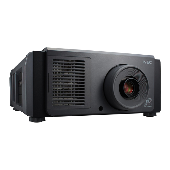
- Page 1 DLP Cinema Projector ® User’s Manual DLP Cinema Projector ® NC1700L Chiller Unit NP-17CU01 Model No. NP-NC1700L...
-
Page 2: Important Information
Important Information Precautions: Please read this manual carefully before This products is classified as Class 4 of IEC60825-1:2007. using your NC1700L and keep the manual handy for future Obey the laws and regulations of your country in relation to reference. the installation and management of the device. - Page 3 • That the connector cable and hose that connects the device to the projector is unplugged WARNING THE END USER IS NOT ALLOWED TO OPEN OR MODIFY THE PRODUCT. NO USER SERVICEABLE PARTS. MAINTAIN AND SERVICE OF THE PRODUCT IS ONLY TO BE HANDLED BY NEC AUTHORIZED TECHNICIANS.
- Page 4 Important Information Power Supply WARNING 1. The projector is so designed that it operates with the power supply voltage described below. 1. Do not cover the lens with the supplied lens cap or • AC200–240V 10.7A (MAX) 50/60Hz Single-phase equivalent while the projector is on. Doing so can Ensure that your power supply fits this requirement lead to distorting or melting of the cap and burning before attempting to use your projector.
- Page 5 Important Information Fire and Shock Precautions Cleaning 1. Ensure that there is sufficient ventilation and that vents 1. Turn off the projector and unplug the power cable before are unobstructed to prevent potentially dangerous con- cleaning the cabinet or replacing the laser. centrations of ozone and the build-up of heat inside your 2.
- Page 6 Telephone: +49 89 99699 0 Fax Line: +49 89 99699 500 Email Address: infomail@nec-displays.com WEB Address: https://www.sharpnecdisplays.eu In North America Company Name: Sharp NEC Display Solutions of America, Inc. Address: 3250 Lacey Rd, Ste 500 Downers Grove, IL 60515 U.S.A. Telephone: +1 866-632-6431 Fax Line: +1 800 356 2415 Email Address: cinema.support@sharpnec-displays.com...
- Page 7 Important Information Laser Aperture Modules • The laser module is equipped in this product. Use of controls or adjustments of procedures other than those specified herein may lead to hazardous laser radiation exposure. • This product is classified as Class 4 of IEC60825-1 Second edition 2007. This product is classified as Class 1 of IEC60825-1 Third edition 2014.
- Page 8 Important Information Label B Label A Laser Aperture (Class4: IEC 60825-1 2nd edition) Label A: Hazard Warning Symbol, Explanatory Label and Label B: Risk Group / Lamp Safety Label Aperture Label Hazard Warning Symbol Aperture Label Explanatory Label...
- Page 9 Important Information Label C Label E Label D Label C: Identification Label Certification Statement Label Label D Label E...
- Page 10 Important Information Chiller unit (NP-17CU01) Label F-Gas Label NP-17CU01 ID Label...
- Page 11 Important Information Laser light specifications Class Class 4 laser product Wavelength Blue: 450 - 460 nm, Red: 636 - 642 nm Maximum optical output Blue (450 - 460 nm): 800 mW, Red (636 - 642 nm): 890 mW Beam diameter 10 mm Divergence 2 Degree to 22 Degree, lens dependent...
- Page 12 Important Information Class 3B Class 1 Class 2 Class 3R Class 4 NP-9LS16ZM1 0.2 m (Tele) 0.1 m (Wide) 0.25 m (Tele) 0.25 m (Wide) 0.9 m (Tele) 1.8 m (Wide) 2.75 m (Tele) Class 3B Class 1 Class 2 Class 3R Class 4 NP-9LS16Z1...
- Page 13 Important Information Class 3B NP-9LS40ZM1 Class 1 Class 2 Class 3R Class 4 NP-9LS40Z 0.3 m (Wide) 0.3 m (Tele) 0.35 m (Wide) 0.35 m (Tele) 1.6 m (Wide) 3.5 m (Tele) 7.5 m (Wide) 9.0 m (Tele) Class 3B Class 1 Class 2 Class 3R...
- Page 14 Important Information Range of Laser Light Emissions The following range indicates the maximum range of emission of laser light. Horizon angle: H Vertical angle: V [Degree] [Degree] Zoom Zoom Lens Lens Tele Wide Tele Wide NP-9LS12ZM1 15.7 22.1 NP-9LS12ZM1 12.2 NP-9LS13ZM1 13.3 20.2...
- Page 15 Important Information Laser radiation range/No entry range (HD:Hazard distance) • The below table describes the radiation range of emitted light by the projector that is classified as Risk Group 3 (RG3) of IEC 62471. • Please keep within bounds for installing the projector. Install a barrier for preventing human eyes from entering the RG3 area.
- Page 16 Important Information CAUTION Please heed all precaution for safety. To install the projector • For planning the layout of the projector, make sure to take safety measures instructed on the installation manual. • In order to refuse danger, install either a wall outlet within easy reach for pulling out the power plug in emergency or a device as a breaker to shut down the power supply to the projector.
-
Page 17: Table Of Contents
Table of Contents Important Information ..............2 1. What’s in the Box? and the Names of the Projector Parts ..18 1-1. Features ..................................18 1-2. What’s in the Box? ..............................20 1-3. Names of the Projector Parts ..........................22 2. -
Page 18: What's In The Box? And The Names Of The Projector Parts
Complies with the strict projection standards defined by the Digital Cinema Initiatives (DCI) industry group in the United States using leading imaging technology of NEC. It also supports 3D projection and high frame rates (HFR). • Employs a long life laser light source The projector employs a newly developed laser light source offering excellent reliability and redundancy. - Page 19 1. What’s in the Box? and the Names of the Projector Parts (3) Frequently used titles can be registered in preset buttons The projector has been equipped with 8 preset buttons that make it easy to select registered title (input signal). To this projector, 100 titles at most can be registered (input signal registration).
-
Page 20: What's In The Box
1. What’s in the Box? and the Names of the Projector Parts 1-2. What’s in the Box? Check the content of the accessories. 1-2-1. Projector Projector Power cable stopper Service door key x 2 Keys for administrator x 2 ... - Page 21 1. What’s in the Box? and the Names of the Projector Parts 1-2-2. Chiller unit (NP-17CU01) Chiller unit (NP-17CU01) In the event that you did not receive all of the accessories outlined above, or some are damaged, contact your dealer/ distributor.
-
Page 22: Names Of The Projector Parts
1. What’s in the Box? and the Names of the Projector Parts 1-3. Names of the Projector Parts 1-3-1. Front of the projector 1. LIGHT status indicator Displays the status of the light source. The indicators turn on when the light source is on and turn off when the light source is off (See page 65). - Page 23 1. What’s in the Box? and the Names of the Projector Parts Contact your dealer/distributor for more information on separately sold optional products. 9. Air inlet The air inlet for cooling inside the projector. Do not cover. 10. Remote interlock connector (inside front of projector) This port is for safely using the laser in this device.
- Page 24 1. What’s in the Box? and the Names of the Projector Parts 1-3-3. Bottom of the projector 1. Handle (4 locations) Handles for moving the projector. 2. Level adjusters (in 4 positions) In the ordinary installation, you can adjust the projector inclination at 4 positions.
- Page 25 1. What’s in the Box? and the Names of the Projector Parts 1-3-4. Chiller unit (NP-17CU01) 1. Coolant inlet of chiller Connects to the attachment port (OUT) of the projector using the hose for the chiller unit. Request your dealer/distributor to attach or detach the hose.
- Page 26 1. What’s in the Box? and the Names of the Projector Parts 1-3-5. Connection terminals 1. Service terminal (REMOTE) (Stereo mini) This terminal is used for service purpose only. 2. Ethernet port (LAN) (RJ-45) The port for interfacing with an image signal server or controlling the projector from a PC via a network. Connect the projector and the PC with a commercially available Ethernet cable (10/100/1000Base-T).
- Page 27 1. What’s in the Box? and the Names of the Projector Parts 1-3-6. Control panel 1. LCD screen The LCD screen displays menus and setting values for the projector operations. 2. /// (UP/DOWN/LEFT/RIGHT) buttons Press these buttons to select a menu item while a menu is displayed. 3.
- Page 28 1. What’s in the Box? and the Names of the Projector Parts 11. IMB button (planned to be supported in a future update) This button is operable when the media block is installed in the projector. Press this button to display the operation menu of the media block. 12.
-
Page 29: Installation And Connection
Installation and Connection 2-1. Steps for setting up and connecting Use the following steps for setting up your projector: • Step 1 Setup the screen and projector and chiller unit. (Contact your dealer to carry out the setup.) • Step 2 Connect the power cable to the projector. -
Page 30: Connecting The Power Cable
2. Installation and Connection 2-2. Connecting the Power Cable The power cable is not included with the projector. Use a power cable that meets the standards and power supply voltage of the country where you are using the projector. Ask your dealer for the power cable to select and purchase. WARNING Carefully read the contents described in this section before connection and connect the cables according to the proper proce- dure. - Page 31 2. Installation and Connection Connect the AC power supply cable. Connect the AC power supply cable to the projector. AC input Connect the power plug to the electrical outlet. This completes the connection of the AC power supply cable.
- Page 32 2. Installation and Connection Using the supplied power cable stopper To prevent the power cable from accidently removing from the AC IN of the projector, attach the supplied power cable stopper to clamp the power cable. CAUTION • To prevent the power cable from coming loose, make sure that all the prongs of the power cable are fully inserted into the AC IN terminal of the projector before using the power cable stopper to fix the power cable.
- Page 33 2. Installation and Connection Slide the clamper to the hilt of the power cable. This completes the attachment of the power cable stopper. Removing the power cable from the power cable stopper Push the clamper of the power cable stopper to unclasp it. knob Push the power cable clamper to open it wide enough to pull out the power cable.
-
Page 34: Connecting The Image Input Terminals
2. Installation and Connection 2-3. Connecting the image input terminals The video input ports that can be used with the IMB are as follows. Refer to the instruction manual of the IMB for details on con- necting the video input ports with external equipment. NP-90MS02 HDMI input port 3G SDI input port... -
Page 35: Projection Of Images (Basic Operation)
Projection of Images (Basic Operation) 3-1. Steps of projecting images • Step 1 Turn on the power to the projector. (See page 36) • Step 2 Select the title of input signal. (See page 38) • Step 3 Adjust the position and size of the projected screen. (See page 39) •... -
Page 36: Turning Your Projector On
3. Projection of Images (Basic Operation) 3-2. Turning your projector on Preparation: • Connect the power cable to the projector (see page 30) and chiller unit. • Supply AC power to the projector and chiller unit. • Turn off the main power switch to the projector when supplying or cutting AC power to the projector. NOTE Supplying or shutting down the AC power while the main power switch is on will damage the projector. - Page 37 3. Projection of Images (Basic Operation) If KEY LOCK is on, press the KEY LOCK button for one second or longer. KEY LOCK becomes off. The KEY LOCK button indicator turns off and buttons on the control panel become operable. (See page 43) Press the POWER button on the control panel of your projector three seconds or longer.
-
Page 38: Selecting The Title Of Input Signal
3. Projection of Images (Basic Operation) 3-3. Selecting the title of input signal This projector allows you to select pre-registered title (input signal) using the preset buttons on the control panel (up to 16 titles). Request your dealer/distributor for details on registering and changing titles. This section explains the steps for selecting registered titles. -
Page 39: Adjusting The Position And The Size Of Projected Screen
3. Projection of Images (Basic Operation) 3-4. Adjusting the position and the size of projected screen 3-4-1. Displaying the test pattern Press the MENU button, or select a test pattern from preset buttons (button <1> to <8>). If you register the test patterns to the preset buttons (<1> to <8> buttons), select the test pattern according to “3-3. Selecting the title of input signal (See page 38)”. - Page 40 3. Projection of Images (Basic Operation) Display on the LCD the name of the test pattern to be projected, then press the ENTER button. The test pattern is displayed. To cancel the test pattern display, select the title of the signal to project or select the “OFF” test pattern. 3-4-2.
- Page 41 3. Projection of Images (Basic Operation) 3-4-3. Adjustment of the size (zoom) and focus of the projected screen Press the MENU button. Press the LEFT/RIGHT button to display “Configuration” on the LCD screen. Press the DOWN button. Press the LEFT/RIGHT button to display “Lens Control” on the LCD screen. Press the DOWN button.
- Page 42 3. Projection of Images (Basic Operation) 3-4-4. Adjusting the brightness of the projected screen (Light output) If the internal temperature within the projector rises due to the temperature in the room being high, the light output NOTE may be automatically reduced. This is called “Thermal Protection Mode (Down Light Power)”. When the projector is in the Thermal Protection Mode, the picture brightness decreases slightly.
-
Page 43: Preventing Misoperations
3. Projection of Images (Basic Operation) 3-5. Preventing misoperations Buttons on the control panel can be locked (KEY LOCK) to prevent misoperations. Buttons on the control panel do not function while KEY LOCK is on. KEY LOCK must be off to operate these buttons. •... -
Page 44: Turning On/Off The Light With The Projector Turned On
3. Projection of Images (Basic Operation) 3-6. Turning on/off the light with the projector turned on The indicators on the control panel blink when the following operations are carried out. (See page 63) NOTE • When you turn the light off The LIGHT ON/OFF button indicator blinks green. -
Page 45: Turning Your Projector Off
3. Projection of Images (Basic Operation) 3-7. Turning your projector off Press the POWER button on the projector control panel for three seconds or longer. The light is turned off, the POWER button indicator blinks green, and the STATUS indicator blinks orange (cooling state). The fan will continue to rotate while cooling, and the amount of time remaining for cooling is displayed on the LCD screen. - Page 46 3. Projection of Images (Basic Operation) Return the laser administrator switch to the OFF position, then remove the laser administrator key. RS-232 GP I/O REMOTE Turn OFF the emergency stop switch (AC power switch) of chiller unit. Turn off the AC power to the projector and chiller unit. In the following instances, do not turn off the main power switch or disconnect the AC power.
-
Page 47: Using Menus
Using Menus 4-1. Basic operation with adjustment menus To adjust the projector, display the menu on the LCD screen of the projector control panel. 4-1-1. Screen display The menu display screen is composed of a menu display field (the upper two lines) and a setting item display field (the bottom two lines). - Page 48 4. Using Menus When not displaying menus, the following screen is normally displayed. When in standby When the projector is in a standby state (the main power switch in on), the following is displayed. When power is turned on When the power is turned on, the following is displayed. ←...
- Page 49 4. Using Menus 4-1-2. Operating menus Preparation: Turn your projector on. (See page 36) Press the MENU button on the control panel of your projector. The menu is displayed in the LCD screen. Press the LEFT/RIGHT buttons to display “Information.” At each press of the LEFT/RIGHT buttons, the display will cycle as “Title Select”...
- Page 50 4. Using Menus Press the DOWN button. The submenu “BIOS” another rank lower than “Model” is displayed. Press the LEFT/RIGHT button to select the submenu “Release Package.” At each press of the LEFT/RIGHT button, the display will cycle as “Model” ←→ “Serial No.” ←→ “Release Package” ←→ “Kernel”...
- Page 51 4. Using Menus 4-1-3. How to enter alphanumeric characters Alphanumeric characters are entered for items, such as the log file of the specified period is written to USB memory. (See page Characters can be entered by pressing numeric buttons on the control panel on this projector. Move right and left Delete entered characters Enter characters...
-
Page 52: Table Of Adjustment Menus
4. Using Menus 4-2. Table of adjustment menus Menus in parentheses are menus for our service personnel. Normally, these menus cannot be used. Reference Main menu Submenu Description page Title Select “Title Memory Name” Selects the title of the signal to be projected. TEST Pattern Selects the test pattern to be projected. -
Page 53: Title Select
4. Using Menus 4-3. Title Select 4-3-1. Title select (Title Memory) Selects the title of the signal to be projected. You can register up to 100 titles. You can also assign registered titles to the preset buttons (<1> to <8> buttons) on the projector’s control panel and call them up directly using those buttons. -
Page 54: Configuration
4. Using Menus 4-4. Configuration Please request your dealer/distributor to perform the settings. 4-4-1. Light Setup Adjust Adjusts the light output (brightness). ← Displays the current output power value (%) when the light rated output is 100%. 4-4-2. Lens Control Adjust the position, size, and focus of the projected screen. - Page 55 4. Using Menus 4-4-3. Reset This is used to reset the light and air filter usage times. Filter Cleaning Resets the air filter usage time (for confirming the filter cleaning time). [1] Press the ENTER button, the confirmation screen will appear. [2] Select “Yes”...
-
Page 56: Title Setup
4. Using Menus 4-5. Title Setup Sets the title to be assigned to the preset buttons (<1> to <8> buttons) (up to 16 titles). Request your dealer/distributor to perform the settings. 4-6. Information Displays the hours of light use, the version information and error codes. 4-6-1. - Page 57 4. Using Menus 4-6-3. Preset Button Sets the title to be assigned to the preset buttons (<1> to <8> buttons) on the projector’s control panel. ← Selects the preset button number whose contents you want to display. ← Displays the assigned title numbers. ←...
- Page 58 4. Using Menus 4-6-6. Version Displays version information about the projector, optional boards, and IMB. System Displays the version information of the projector. ← Selects the item to display. ← Displays the version information. • Model • Serial No. • Release Package •...
- Page 59 4. Using Menus 4-6-8. Setup Date Displays the date when the projector was set up (starting date of the warranty period). ← Displays the date when the projector was set up (starting date of the warranty period). 4-6-9. Option Status Displays the link status of the device mounted in slot on the projector.
-
Page 60: Maintenance Of Your Projector
Maintenance of Your Projector Please request your dealer to perform cleaning of the projector inside. NOTE 5-1. Cleaning the Cabinet Before carrying out maintenance of your projector and chiller unit, be sure to always check that the projector is turned off and the power plug is unplugged from the electrical outlet. -
Page 61: Cleaning The Lens
5. Maintenance of Your Projector 5-2. Cleaning the Lens Clean the lens the same way as with camera lens (using a commercially available camera blower or cleaning paper for glasses). Take care not to damage the lens when cleaning. -
Page 62: Appendix
Appendix 6-1. Troubleshooting Before asking for repair, please check your connection, settings and operation once again. If the trouble cannot be corrected, please contact your dealer/distributor for instructions or repair. 6-1-1. Problems and where to check Problem Check these items The projector cannot be turned on. -
Page 63: Indicator Display List
6. Appendix Problem Check these items Video image is disturbed. Check whether the signal cable connected to the projector is disconnected. The STATUS indicator blinks in red. Your projector may have trouble. Please contact your dealer/distributor for instructions. An error code is displayed. Please contact your dealer/distributor for instructions. - Page 64 6. Appendix 6-2-3. POWER button Indicator condition Projector condition Note The projector power supply is off. Blinking light Orange While the projector software is starting Wait for a moment. Green Preparing to turn power on/cooling fan rotating Wait for a moment. (cycles of 1) (State from turning the power off to entering standby mode).
- Page 65 6. Appendix 6-2-6. STATUS indicator LIGHT status indicator SYSTEM status indicator SYSTEM status indicator Indicator condition Projector condition Note Main power is off. Blinking light Green The projector is getting ready to turn on. Wait for a moment. The douser is closed. The light is off.
-
Page 66: Operation Using An Http Browser
“HOSTS” file of the computer being used. (Example 1) When the host name of the projector has been set to “pj.nec.co.jp” http://pj.nec.co.jp/index.html is specified for the address or the entry column of the URL to access HTTP server functions. - Page 67 6. Appendix 6-3-4. Structure of the HTTP server Power Controls the power to your projector. • On: Turns the power on. • Off: Turns the power off. Light Turn the light on/off. • On: Turns the light on. • Off: Turns the light off. Title List Displays titles set in the projector (such as input port, screen type, and title).
-
Page 68: Writing Of The Log File (Save Information)
6. Appendix 6-4. Writing of the log file (Save Information) Log files saved on the main unit can be written to USB memory connected to the USB port of the main unit. To perform the writing of the log file, use the following procedure. Connect the USB memory to the USB port of the main unit. - Page 69 6. Appendix When “Manual” is selected, specify the log file writing period. For how to enter numerals, refer to “4-1-3. How to enter alphanumeric characters” (See page 51). If you press the ENTER button, the display advances to the following screen. ←...
- Page 70 6. Appendix 6-4-1. Names of log files Written log files are saved with the following file names. (Model name)_(Serial Number)_YYMMDDHHmm.txt (Model name) This shows the model of projector. (Serial Number) This shows the serial number of projector. YYMMDDHHmm Shows the date/time when written. YY: Year (lower 2 digits) MM: Month (2 digits) DD: Date (2 digits)
-
Page 71: Outline Drawing
6. Appendix 6-5. Outline Drawing 6-5-1. Projector (84) Units: mm... - Page 72 6. Appendix 6-5-2. Chiller unit (NP-17CU01) Units: mm...
-
Page 73: Specifications
6. Appendix 6-6. Specifications 6-6-1. Projector Model name NC1700L Projection method 3 chip DLP Cinema® method 0.69-inch DC2K chip Panel resolution 2048 x 1080 Light type Red, blue : Laser diode Green : Blue laser diode + Phosphor Screen sizes Max. - Page 74 6. Appendix 6-6-2. Chiller unit Model name NP-17CU01 Power supply voltage AC 200 to 240 V 50 Hz, AC 220 to 240 V 60 Hz single phase Input current 9.2 A (50 Hz) / 10.3 A (60 Hz) Power consumption 1610 W (50 Hz) / 2000 W (60 Hz) Net weight 108 kg...
-
Page 75: Power Cable
6. Appendix 6-7. Power Cable Ask your dealer for the power cable to select and purchase. NOTE Power Cable Electrical Specification The projector is equipped with an IEC60320 C19 connector to connect an AC power supply cable. Ensure that the AC power cables that connect the connectors built into the projector to the AC power maintains the current capacities as shown below. - Page 76 6. Appendix Japan Plug Cable Connector JIS C 8303 VCTF 3 x 2.0mm IEC 320 C19 China Plug Cable Connector GB2099 RVV 300/500 GB17465.1 Connector Dimensions of the connector of the power cable are shown below. -0.9 -0.7 ± +0.5 + 0.5 R3.5 min +0.5...
-
Page 77: Pin Assignment And Functions Of Terminal
6. Appendix 6-8. Pin Assignment and Functions of Terminal 6-8-1. PC CONTROL connector (RS-232) (D-sub 9 pin) This is an RS-232C interface for controlling the projector from a PC. The projector operates as a DCE (Data Communication Equipment), so use a straight cable when connecting to a PC. Pin No. - Page 78 6. Appendix 6-8-2. External control connector (GP I/O) (D-sub 37 pin) It is possible to control the projector with an external device and to control the external device from the projector using an external control connector (GPIO: General Purpose I/O Ports). Each pin is electrically separated from the projector internal circuits by a photo-coupler.
- Page 79 6. Appendix Input Connector GP I/O Connector Inside Projector Resist = 390 Ω Ext_GPIN_P Pin No.: Voltage applied across the pins of Ext_GPIN_P and Ext_GPIN_N should be in the range from 3.3 Vdc to 10 Vdc. Recommended Operating Current: Absolute Maximum Rating: 23mA Ext_GPIN_N Pin No.: 20 21 23 23 24 25 26 27...
- Page 80 6. Appendix • Timing chart of GPIO control Example of Select Preset Button Off at least 500 ms at least 500 ms approx. 200 ms 8-27 5-24/6-25/7-26 time Execute Select Preset Button Example for turning the image douser (Douser) on Off at least 500 ms at least 500 ms approx.
- Page 81 6. Appendix Example of Light source On Off at least 500 ms at least 500 ms approx. 200 ms 5-24/6-25 7-26/8-27 time Execute Light source On Example for turning the power off Off at least 500 ms at least 500 ms approx.
- Page 82 6. Appendix Output Connector GP I/O Connector Inside Projector Ext_GPOUT_P Ext_PROJ_GOOD_P Pin No.: 9 10 11 12 13 14 15 16 Absolute Maximum Rating: 50 mA Ext_GPOUT_N Ext_PROJ_GOOD_N Pin No.: 28 29 30 31 32 33 34 35 Photo-coupler • Using GPIO Control You can use GPIO control for the projector’s health check and error check.
- Page 83 6. Appendix 6-8-3. 3D connector (D-sub 15 pin) This is used to connect a 3D image system to the projector. Pin view of a female connector Pin No. Signal Name Function +12V Supplies power (+12V) to the 3D image system GNDC Ground GNDC...
-
Page 84: Related Products List
6. Appendix 6-9. Related products list Product name Lens memory support Model name Lens Zoom lens 1.63 to 2.03 – NP-9LS16Z1 Zoom lens 2.03 to 2.72 – NP-9LS20Z1 Zoom lens 4.07 to 6.34 – NP-9LS40Z Zoom lens 1.2 to 1.72 NP-9LS12ZM1 Zoom lens 1.33 to 2.1 ... - Page 85 © NEC Display Solutions, Ltd. 2016 Ver. 2 2/21...
Need help?
Do you have a question about the DLP Cinema NC1700L and is the answer not in the manual?
Questions and answers