
Related Manuals for Riello Burners PRESS 30N


Summary of Contents for Riello Burners PRESS 30N
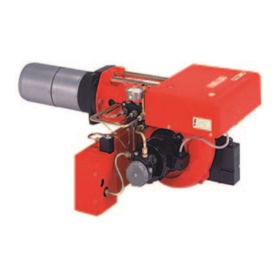
- Page 1 Installation, use and maintenance instructions Heavy oil burner CODE MODEL TYPE 3433785 PRESS 30N 614 T80 3433786 PRESS 30N 614 T80 2915893 (2) - 01/2009...
- Page 3 Thermal power - Output 85 / 171 - 342 kW - 7.5 / 15 - 30 kg/h Operation Two stages Fuel Oil with max. viscosity at 50 °C: 150 mm /s (20 °E) 220V +10% -10% ~ 60Hz without neutral Electrical supply (3 phase) 380V +10% -10% ~ 60Hz with neutral Motor...
- Page 4 COMBUSTION CHAMBER PRESSURE - MAXIMUM OUTPUT (two nozzles in operation) When the burner operates with only one nozzle, the pressurization conditions are improved and no problems arise. Minimal fuel capacity with only one nozzle: 7.5 kg/h - 85 kW Front plate detail for boiler mounting Note for the extend.
- Page 5 FUEL OIL GRAVITY FEED SYSTEMS Gravity system (fuel oil with viscosity max. 7°E at 50° C) L meters Pump priming: loose the tap of the ø 3/4” ø 1” meters vacuometer plug 5) (fig. 1) and wait for the fuel flow. H: Difference in the pipes height.
-
Page 6: Electrical Wiring Connections
ELECTRICAL WIRING CONNECTIONS (carried out by the factory) RMO88.53A2 RMO88.53A2 12 15 1 3 5 S3 T1 30 T2 T6 T8 D2599 LEGEND CMV Fan motor contactor Pre-heart Servomotor Pre-heart contactor Ignition transformer Suppressor Earth of the burner Photoresistance Start-up and adjustment thermostat Wiring terminal board Minimum value contact thermostat Fan motor... - Page 7 ELECTRICAL CONNECTIONS TO THE WIRING TERMINAL BOARD (to be carried out by the installer) D2463 KEY TO LAYOUT Remote lock-out signal 220V 380V Manual burner stop switch A Ampere Wiring terminal board B mm Limit control device system High-low mode control device system Safety control device system NOTICE: Leads minimal section 1,5 mm TWO STAGE OPERATION...
- Page 8 FASTENING OF THE ELECTRICAL WIRES All the electrical wires, which are to be connected to the terminal board 16) (fig. 1) shall pass through the fair leads 17) (fig. 1) as per this scheme 1 - Pre-heating resistances single phase supply: fair lead Pg 21 2 - Motor three phase supply: fair lead Pg 16 3 - Single phase supply and safety thermostat:...
- Page 9 CHOICE OF NOZZLES - OF THE PUMP PRESSURE OF THE COMBUSTION HEAD ADJUSTMENT Nozzles delivery Combustion head adjustment Pump pressure Maximum output Nozzle 20 bar 25 bar GPH (45° - 60°) kg/h kg/h 1,25 + 1,25 15,00 17,00 1,50 + 1,50 18,00 20,30 1,75 + 1,75...
- Page 10 ADJUSTMENT OF THE AIR DAMPER MOTOR STOP - Blue lever This lever leaves the factory vertically positioned and Black lever corresponds to the complete closing of the air damp- Red lever A partial opening of the air damper might be obtained by moving leftwards this lever (+ on the label).
- Page 11 SPRAY TEMPERATURE ADJUSTMENT Thermostat for adjustment - maximum value - minimum value Adjustment thermostat: it prevents the burner start up if the fuel temperature has not reached the required val- ue for a good spray as indicated in the diagram below. Sheath for thermometer Adjusting knob...
- Page 12 NOTES 1 - The pre-heater might be provided with a second thermostat of maximum value with manual reset. That thermostat can be used as a switch operating by means of an external commutator, which can take off the current from the pre-heater in case of over-temperature. (Kit code no. 3000800). 2 - The resistance R placed on the nozzle-holder is wired to the supply line of the pre-heater (see drawing page 4).
-
Page 13: Burner Start-Up Cycle Diagnostics
BURNER START-UP CYCLE DIAGNOSTICS During start-up, indication is according to the followin table: COLOUR CODE TABLE Sequences Colour code Pre-purging Ignition phase Operation, flame ok Operating with weak flame signal Electrical supply lower than ~ 170V Lock-out Extraneous light Key: Yellow Green OPERATING FAULT DIAGNOSTICS... - Page 16 RIELLO S.p.A. I-37045 Legnago (VR) Tel.: +39.0442.630111 http:// www.rielloburners.com Subject to modifications...
Need help?
Do you have a question about the PRESS 30N and is the answer not in the manual?
Questions and answers