Table of Contents
Advertisement
Available languages
Available languages
Quick Links
Istruzioni per installazione, uso e manutenzione / Catalogo ricambi
Montage und Bedienungsanleitung / Ersatzteile Katalog
Manuel d'entretien / Catalogue pièces détachées
Installation, use and maintenance instructions / Spare parts list
Installatie-, gebruiks- en onderhoudsvoorschriften / Onderdelencatalogus
Instrucciones de instalación, uso y mantenimiento / Catálogo recambios
I
Rampe gas monostadio
D
Einstufige Gasstrecken
F
Rampe gaz a une allure
st
GB
1
stage gas trains
NL
Gasstraat - eentraps
E
Rampe de gas a 1 llama
CODICE - CODE
3970144 - 3970197 - 3970231 - 3970256
3970180 - 3970198 - 3970232 - 3970250
3970181 - 3970182 - 3970233 - 3970234
3970252 - 3970257
CÓDIGO
3970229
3970230
3970253
MODELLO - MODELL - MODELE
MODEL - MODELO
MB 407/1
MB 410/1
MB 412/1
MB 415/1
MB 420/1
20049141 (1) - 03/2012
Advertisement
Table of Contents

Related Manuals for Riello Burners MB 407/1


Summary of Contents for Riello Burners MB 407/1
- Page 1 Rampe de gas a 1 llama CODICE - CODE MODELLO - MODELL - MODELE CÓDIGO MODEL - MODELO 3970229 MB 407/1 3970230 MB 410/1 3970144 - 3970197 - 3970231 - 3970256 MB 412/1 3970180 - 3970198 - 3970232 - 3970250...
- Page 3 Informazioni ed avvertenze generali Informazioni ed avvertenze generali Informazioni sul manuale di istruzione 1.1.1 Introduzione In caso di danneggiamento o smarrimento deve essere richiesto un altro esemplare al Servizio Tecnico di Assi- Il manuale di istruzione dato a corredo della rampa gas: stenza di Zona;...
- Page 4 Sicurezza e prevenzione Sicurezza e prevenzione Premessa E’ necessario tenere in considerazione che l’incauto e maldestro sicurezza tecnica ineccepibili. Eventuali disturbi che pos- utilizzo della rampa gas può causare situazioni di pericolo di mor- sano compromettere la sicurezza devono essere eliminati te per l’utente o terzi, nonchè...
-
Page 5: Descrizione Tecnica
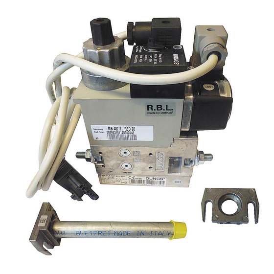
Modelli disponibili Codice Modello Codice Modello 3970233 MB 420/1 - RSM 30 3970229 MB 407/1 - RSM 20 3970234 MB 420/1 CT RSM 30 3970230 MB 410/1 - RSM 20 3970252 MB 420/1 CT RT 52 3970144 MB 412/1 - RT 20... - Page 6 Presa di pressione (MB 415-420/1) Viti fissaggio flangia Regolazione stabilizzatore Regolazione freno Ghiera regolazione portata Vite bloccaggio ghiera (non sigillata) Pressostato gas di minima Controllo di tenuta (versioni CT) 10 Bobina 11 Presa di pressione (MB 407/1) 12 Presa di pressione (MB 410-412/1) 20049141...
- Page 7 Descrizione tecnica Dimensioni d’ingombro L’ingombro della rampa è riportato in Fig. 2. 20049755 Fig. 2 ØD ØE Codice (Rete) (Bruciatore) 4 - 30 mbar (*) 3970229 Rp 3/4 Rp 3/4 4 - 50 mbar (**) 3970230 Rp 1” Rp 3/4 3970144 Rp 1”...
-
Page 8: Installazione
Installazione Installazione Note sulla sicurezza per l’installazione Dopo avere effettuato un’accurata pulizia tutt’intorno all’area de- L’installazione della rampa deve essere effettuata stinata all’installazione della rampa ed avere provveduto ad una da personale abilitato, secondo quanto riportato corretta illuminazione dell’ambiente, procedere con le operazioni nel presente manuale ed in conformità... - Page 9 Installazione Installazione rampa gas Le rampe gas sono predisposte per essere installate alla sinistra del bruciatore: in caso di montaggio sulla destra, è necessario Controllare che non vi siano fughe di gas. spostare sul lato opposto la presa di pressione (Fig. 1, pag. 4) e (se presente) il controllo di tenuta 9)(Fig.
- Page 10 Le rampe gas riportate in Tab. D sono predisposte in fabbrica per essere collegata secondo lo schema elettrico riportato in Fig. 5. Codice Modello 3970229 MB 407/1 - RSM 20 3970230 MB 410/1 - RSM 20 3970231 MB 412/1 - RSM 20...
- Page 11 Installazione Le rampe gas riportate in Tab. G sono predisposte in fabbrica per essere collegata secondo lo schema elettrico riportato in Fig. 8. Codice Modello 3970197 MB 412/1 CT RT 20 3970198 MB 415/1 CT RT 30 3970182 MB 420/1 CT RT 30 Tab.
- Page 12 Messa in funzione, taratura e funzionamento Messa in funzione, taratura e funzionamento Note sulla sicurezza per la prima messa in funzione La prima messa in funzione della rampa deve es- Verificare la corretta funzionalità dei dispositivi di sere effettuata da personale abilitato, secondo regolazione, comando e sicurezza.
- Page 13 Messa in funzione, taratura e funzionamento Perdita di carico La perdita di carico p della rampa viene fornita dal diagramma I valori forniti dal diagramma possono variare leggermente in fun- V ° (Fig. 10); le scale della portata volumetrica valgono rispetti- zione della regolazione dello stabilizzatore di pressione.
-
Page 14: Manutenzione
Manutenzione Manutenzione Note sulla sicurezza per la manutenzione La manutenzione periodica è essenziale per il buon funziona- mento, la sicurezza, il rendimento e la durata della rampa gas. Togliere l’alimentazione elettrica, agendo sull’in- Essa consente di ridurre i consumi, le emissioni inquinanti e di terruttore generale dell’impianto. - Page 15 Allgemeine Informationen und Hinweise Allgemeine Informationen und Hinweise Informationen zur Bedienungsanleitung 1.1.1 Einleitung Bei Beschädigung oder Verlust muss ein anderes Exemplar beim gebietszuständigen Technischen Kundendienst ange- Die der Gasarmatur beiliegende Bedienungsanleitung: fordert werden; stellt einen wesentlichen und integrierenden Teil des Pro- ...
- Page 16 Sicherheit und Vorbeugung Sicherheit und Vorbeugung Einleitung Der Einsatz der Gasarmatur muss unter einwandfreien Es muss beachtet werden, dass die unvorsichtige und unge- schickte Verwendung der Gasarmatur zu Situationen führen Sicherheitsbedingungen erfolgen. Eventuelle Störungen, die kann, bei denen Todesgefahr für den Benutzer oder Dritte, sowie die Sicherheit beeinträchtigen können, müssen umgehend die Möglichkeit von Beschädigungen am Brenner oder anderen beseitigt werden.
-
Page 17: Technische Beschreibung
Erhältliche Modelle Code Modell Code Modell 3970233 MB 420/1 - RSM 30 3970229 MB 407/1 - RSM 20 3970234 MB 420/1 CT RSM 30 3970230 MB 410/1 - RSM 20 3970252 MB 420/1 CT RT 52 3970144 MB 412/1 - RT 20... - Page 18 Beschreibung 20050020 Abb. 1 Flansch Druckentnahmestelle (MB 415-420/1) Befestigungsschrauben für Flansch Einstellung des Stabilisators Bremsregulierung Nutmutter für die Durchsatzregulierung Befestigungsschraube für die Nutmutter (nicht versiegelt) Minimal-Gasdruckwächter Dichtheitskontrolle (CT Ausführungen) 10 Spule 11 Druckentnahmestelle (MB 407/1) 12 Druckentnahmestelle (MB 410-412/1) 20049141...
- Page 19 Technische Beschreibung Abmessungen Der Platzbedarf der Gasarmatur ist in Abb. 2 angegeben. 20049755 Abb. 2 ØD ØE Code (Netz) (Brenner) 4- 30 mbar (*) 3970229 Rp 3/4 Rp 3/4 4- 50 mbar (**) 3970230 Rp 1” Rp 3/4 3970144 Rp 1”1/4 Rp 1”1/4 D10008 3970197...
-
Page 20: Installation
Installation Installation Sicherheitshinweise für die Installation Nehmen Sie die Installation nach einer sorgfältigen Reinigung Die Installation der Gasarmatur muss durch Fach- des gesamten zur Installation der Gasarmatur bestimmten Be- personal gemäß den Angaben in diesem Hand- reichs und einer korrekten Beleuchtung des Raums vor. buch sowie in Übereinstimmung mit den gültigen Alle Arbeiten zur Installation, Wartung und De- ACHTUNG... - Page 21 Installation Installation der Gasarmatur Die Gasarmaturen wurden für die Montage auf der linken Seite des Brenners vorgerüstet: Bei rechtsseitiger Montage muss die Kontrollieren Sie, ob Gas austritt. Druckentnahmestelle (Abb. 1 Seite 4) und (wenn vorhanden) auch die Dichtheitskontrolle 9)(Abb. 1 Seite 4) auf die gegen- überliegende Seite versetzt werden.
- Page 22 Die in Tab. D angeführten Gasarmaturen wurden werkseitig für den Anschluss laut dem in Abb. 5 angeführten Schaltplan vorge- rüstet. Code Modell 3970229 MB 407/1 - RSM 20 3970230 MB 410/1 - RSM 20 3970231 MB 412/1 - RSM 20 3970232...
- Page 23 Installation Die in Tab. G angeführten Gasarmaturen wurden werkseitig für den Anschluss laut dem in Abb. 8 angeführten Schaltplan vorge- rüstet. Code Modell 3970197 MB 412/1 CT RT 20 3970198 MB 415/1 CT RT 30 3970182 MB 420/1 CT RT 30 Tab.
- Page 24 Inbetriebnahme, Einstellung und Betrieb Inbetriebnahme, Einstellung und Betrieb Sicherheitshinweise für die erstmalige Inbetriebnahme Die erstmalige Inbetriebnahme der Armatur muss Prüfen Sie die richtige Funktionsweise der Ein- durch zugelassenes Fachpersonal gemäß den stell-, Steuer- und Sicherheitsvorrichtungen. Angaben in diesem Handbuch sowie in Überein- ACHTUNG stimmung mit den gültigen gesetzlichen Normen ACHTUNG...
- Page 25 Inbetriebnahme, Einstellung und Betrieb Druckverlust Der Druckverlust p der Gasarmatur ist dem obigen Diagramm Die im Diagramm angegebenen Werte können je nach Einstel- V ° zu entnehmen (Abb. 10); Die Skala der Durchsatzmenge lung des Druckstabilisators variieren. gelten jeweils für: Der notwendige Mindestdruck im Netz wird erzielt, indem die Luft, Druckverluste des Brenners (siehe Brenneranleitung) und der...
-
Page 26: Wartung
Wartung Wartung Sicherheitshinweise für die Wartung Die regelmäßige Wartung ist für die gute Funktionsweise, die Si- cherheit, die Leistung und Nutzungsdauer der Gasarmatur we- Schalten Sie die Stromversorgung durch Betäti- sentlich. gen des Hauptschalters der Anlage ab. Sie ermöglicht es, den Verbrauch und die Schadstoffemissionen GEFAHR zu verringern sowie das Produkt im Zeitverlauf zuverlässig zu er- halten. -
Page 27: Informations Et Avertissements Généraux
Informations et avertissements généraux Informations et avertissements généraux Informations sur le manuel d’instructions 1.1.1 Introduction déplacée sur une autre installation. S’il a été endommagé ou égaré demander une autre copie Le manuel d’instructions fourni avec la rampe gaz: au service d’assistance à la clientèle de Zone; ... -
Page 28: Sécurité Et Prévention
Sécurité et prévention Sécurité et prévention Avant-propos L’utilisation de la rampe gaz doit se faire dans des condi- Il est cependant nécessaire de tenir compte du fait qu’une utilisa- tion imprudente ou maladroite de la rampe gaz peut provoquer tions de sécurité... -
Page 29: Description Technique
Modèles disponibles Code Modèle Code Modèle 3970233 MB 420/1 - RSM 30 3970229 MB 407/1 - RSM 20 3970234 MB 420/1 CT RSM 30 3970230 MB 410/1 - RSM 20 3970252 MB 420/1 CT RT 52 3970144 MB 412/1 - RT 20... - Page 30 Réglage du stabilisateur Réglage frein Bague de réglage du débit Vis de blocage de la bague (non scellée) Pressostat gaz seuil minimum Contrôle d’étanchéité (versions CT) 10 Bobine 11 Prise de pression (MB 407/1) 12 Prise de pression (MB 410-412/1) 20049141...
- Page 31 Description technique Dimensions d’encombrement L’encombrement de la rampe gaz est indiqué dans la Fig. 2. 20049755 Fig. 2 ØD ØE Code (Réseau) (Brûleur) 4 - 30 mbar (*) 3970229 Rp 3/4 Rp 3/4 4 - 50 mbar (**) 3970230 Rp 1” Rp 3/4 3970144 Rp 1”1/4...
- Page 32 Installation Installation Indications concernant la sécurité pour l’installation Après avoir nettoyé soigneusement tout autour de la zone où la L’installation la rampe doit être effectuée par du rampe doit être installée et à avoir bien éclairé le milieu, effectuer personnel habilité, selon les indications reportées les opérations d’installation.
- Page 33 Installation Installation de la rampe gaz Les rampes gaz sont prévues pour être montées à gauche du brûleur: en cas de montage sur la droite, il est nécessaire de dé- Contrôler l’absence de fuites de gaz. placer sur le côté opposé la prise de pression (Fig. 1, page 4) et (le cas échéant) le contrôle d’étanchéité...
- Page 34 Les rampes gaz indiquées dans le Tab. D sont prévues en usine pour être branchées selon le schéma électrique indiqué sur la Fig. 5. Code Modèle 3970229 MB 407/1 - RSM 20 3970230 MB 410/1 - RSM 20 3970231 MB 412/1 - RSM 20 3970232...
- Page 35 Installation Les rampes gaz indiquées dans le Tab. G sont prévues en usine pour être branchées selon le schéma électrique indiqué sur la Fig. 8. Code Modèle 3970197 MB 412/1 CT RT 20 3970198 MB 415/1 CT RT 30 3970182 MB 420/1 CT RT 30 Tab.
- Page 36 Mise en service, réglage et fonctionnement Mise en service, réglage et fonctionnement Indications concernant la sécurité pour la première mise en marche La première mise en marche de la rampe doit être Vérifier le bon fonctionnement des dispositifs de effectuée par un personnel habilité, selon les indi- réglage, de commande et de sécurité.
- Page 37 Mise en service, réglage et fonctionnement Perte de charge La perte de charge p de la rampe est fournie par le diagramme Les valeurs fournies par le diagramme peuvent varier légèrement V ° (Fig. 10); les échelles du débit volumétrique ont respective- selon le réglage du stabilisateur de pression.
-
Page 38: Entretien
Entretien Entretien Indications concernant la sécurité pour l’entretien L’entretien périodique est indispensable pour un bon fonctionne- ment, la sécurité, le rendement et la durée de vie de la rampe Couper l’alimentation électrique en appuyant sur gaz. l’interrupteur général de l’installation. Il permet de réduire la consommation, les émissions polluantes DANGER et au produit de rester fiable dans le temps. -
Page 39: Information And General Warnings
Information and general warnings Information and general warnings Information about the instruction manual 1.1.1 Introduction If the manual is lost or damaged, another copy must be requested from the Technical Assistance Service of the The instruction manual supplied with the gas train: area;... -
Page 40: Safety And Prevention
Safety and prevention Safety and prevention Introduction The gas train must be used in impeccably secure conditions. It is necessary, however, to bear in mind that the imprudent and clumsy use of the gas train may lead to situations of death risk for Any disturbances that could compromise safety must be the user or third parties, as well as the damaging of the burner or quickly eliminated. -
Page 41: Technical Description
Models available Code Model Code Model 3970233 MB 420/1 - RSM 30 3970229 MB 407/1 - RSM 20 3970234 MB 420/1 CT RSM 30 3970230 MB 410/1 - RSM 20 3970252 MB 420/1 CT RT 52 3970144 MB 412/1 - RT 20... - Page 42 Flange fastening screws Stabiliser adjustment Brake adjustment Ring nut output adjustment Ring nut locking screws (not sealed) Minimum gas pressure switch Leak detection control device (CT versions) 10 Coil 11 Pressure test point (MB 407/1) 12 Pressure test point (MB 410-412/1) 20049141...
- Page 43 Technical description Maximum dimensions The maximum dimensions of the train are given in Fig. 2. 20049755 Fig. 2 ØD ØE Code (Network) (Burner) 4 - 30 mbar (*) 3970229 Rp 3/4 Rp 3/4 4 - 50 mbar (**) 3970230 Rp 1” Rp 3/4 3970144 Rp 1”...
- Page 44 Installation Installation Notes on safety for the installation After carefully cleaning all around the area where the train will be Train installation must be carried out by qualified installed, and arranging the correct lighting of the environment, personnel, as indicated in this manual and in com- proceed with the installation operations.
- Page 45 Installation Gas train installation The gas trains are intended to be installed to the left of the burner: if fitted to the right, it will be necessary to move the pressure test Check that there are no gas leaks. point to the opposite side (Fig. 1, page 4),as well as the leak de- tection control 9) (if present) (Fig.
- Page 46 The gas trains shown in Tab. D are prepared in the factory to be connected in accordance with the electrical diagram shown in Fig. 5. Code Model 3970229 MB 407/1 - RSM 20 3970230 MB 410/1 - RSM 20 3970231 MB 412/1 - RSM 20 3970232...
- Page 47 Installation The gas trains shown in Tab. G are prepared in the factory to be connected in accordance with the electrical diagram shown in Fig. 8. Code Model 3970197 MB 412/1 CT RT 20 3970198 MB 415/1 CT RT 30 3970182 MB 420/1 CT RT 30 Tab.
- Page 48 Activation, calibration and functioning Activation, calibration and functioning Notes on safety for the first start-up The first start-up of the burner must be carried out Check the correct working of the adjustment, com- by qualified personnel, as indicated in this manual mand and safety devices.
- Page 49 Activation, calibration and functioning Pressure loss The gas train pressure loss p is provided from the diagram (Fig. The values, provided from the diagram, can be different accord- V ° 10); the scales of the volumetric output are valid respectively ing to the pressure regulator calibration.
-
Page 50: Maintenance
Maintenance Maintenance Notes on safety for the maintenance The periodic maintenance is essential for the good operation, safety, yield and duration of the gas train. Disconnect the electrical power using the main It allows you to reduce consumption and polluting emissions and switch. -
Page 51: Algemene Informatie En Waarschuwingen
Algemene informatie en waarschuwingen Algemene informatie en waarschuwingen Informatie over de handleiding 1.1.1 Inleiding In geval van beschadiging of verlies moet u een ander exemplaar aanvragen bij de Technische Hulpdienst in uw De handleiding die samen met de gasstraat geleverd wordt: buurt;... -
Page 52: Veiligheid En Preventie
Veiligheid en preventie Veiligheid en preventie Inleiding De gasstraat moet gebruikt worden in onberispelijke tech- Onvoorzichtig en onhandig gebruik van de gasstraat kan gevaar- lijke situaties, en zelfs de dood, veroorzaken voor de gebruiker of nisch veilige omstandigheden. Eventuele storingen die de voor derden, evenals beschadigingen van de brander of andere veiligheid negatief kunnen beïnvloeden moeten tijdig geëli- goederen. -
Page 53: Technische Beschrijving
Beschikbare modellen Code Model Code Model 3970233 MB 420/1 - RSM 30 3970229 MB 407/1 - RSM 20 3970234 MB 420/1 CT RSM 30 3970230 MB 410/1 - RSM 20 3970252 MB 420/1 CT RT 52 3970144 MB 412/1 - RT 20... - Page 54 Regelventiel met trage opening ..... . N. 1 Beschrijving 20050020 Fig. 1 Flens Drukafnamepunt (MB 415-420/1) Bevestigingsschroeven flens Regeling stabilisator Regeling rem Moer regeling debiet Blokkeerschroef moer (niet verzegeld) Minimum gasdrukschakelaar Dichtingscontrole (versies CT) 10 Spoel 11 Drukafnamepunt (MB 407/1) 12 Drukafnamepunt (MB 410-412/1) 20049141...
- Page 55 Technische beschrijving Afmetingen De afmetingen van de gasstraat worden aangeduid in Fig. 2. 20049755 Fig. 2 ØD ØE Code (Net) (Brander) 4 - 30 mbar (*) 3970229 Rp 3/4 Rp 3/4 4 - 50 mbar (**) 3970230 Rp 1” Rp 3/4 3970144 Rp 1”1/4 Rp 1”1/4...
- Page 56 Installatie Installatie Aantekeningen over de veiligheid bij de installatie Nadat het gebied rondom de zone van de installatie van de gas- De installatie van de gasstraat moet uitgevoerd straat zorgvuldig is gereinigd en een gepaste verlichting van de worden door bevoegd personeel, volgens de aan- omgeving is voorzien, kunnen de handelingen van de installatie duidingen in deze handleiding en in overeenstem- begonnen worden.
- Page 57 Installatie Installatie gasstraat De gasstraten zijn voorzien om op de linker kant van de brander gemonteerd te worden: in geval van een montage op de rechter Controleer of geen gaslekken aanwezig zijn. kant, moeten het drukafnamepunt (Fig. 1, pag. 4) en (indien aan- wezig) de dichtingscontrole 9)(Fig.
- Page 58 De gasstraten die worden aangeduid in Tab. D zijn in de fabriek voorzien voor de aansluiting volgens het elektrische schema dat wordt aangeduid in Fig. 5. Code Model 3970229 MB 407/1 - RSM 20 3970230 MB 410/1 - RSM 20 3970231 MB 412/1 - RSM 20 3970232...
- Page 59 Installatie De gasstraten die worden aangeduid in Tab. G zijn in de fabriek voorzien voor de aansluiting volgens het elektrische schema dat wordt aangeduid in Fig. 8. Code Model 3970197 MB 412/1 CT RT 20 3970198 MB 415/1 CT RT 30 3970182 MB 420/1 CT RT 30 Tab.
- Page 60 Inbedrijfstelling, ijking en werking Inbedrijfstelling, ijking en werking Aantekeningen over de veiligheid bij de eerste inbedrijfstelling De eerste inbedrijfstelling van de gasstraat moet Controleer of de mechanismen voor regeling, be- uitgevoerd worden door bevoegd personeel, vol- diening en veiligheid correct functioneren. gens de aanduidingen in deze handleiding en in AANDACHT overeenstemming met de geldende normen en...
- Page 61 Inbedrijfstelling, ijking en werking Drukverlies De grafiek geeft de drukverliezen p van de gasstraat aan De waarden die worden aangeduid op het diagram kunnen licht- V ° (Fig. 10) de schalen van het volumedebiet gelden voor: jes variëren in functie van de regeling van de drukstabilisator. lucht, De minimale druk die noodzakelijk is in het gasnet wordt verkre- aardgas (G20),...
- Page 62 Onderhoud Onderhoud Opmerkingen over de veiligheid voor het onderhoud Het periodieke onderhoud is van essentieel belang voor de cor- recte functionering, de veiligheid, het rendement en de duur- Onderbreek de stroomtoevoer met de hoofdscha- zaamheid van de gasstraat. kelaar van de inrichting. Dankzij het onderhoud worden het verbruik en de vervuilende uit- GEVAAR stoten gereduceerd en blijft het product betrouwbaar door de tijd...
-
Page 63: Informaciones Y Advertencias Generales
Informaciones y advertencias generales Informaciones y advertencias generales Información sobre el manual de instrucciones 1.1.1 Introducción ferencia a otra instalación. En caso de daño o extravío debe solicitarse otro ejemplar al El manual de instrucción entregado junto con la rampa de gas: Servicio Técnico de Asistencia de la Zona;... -
Page 64: Seguridad Y Prevención
Seguridad y prevención Seguridad y prevención Introducción Es necesario considerar que usar la rampa gas de modo impru- de seguridad técnica irreprochables. Los eventuales incon- dente y sin experiencia puede causar situaciones de peligro mor- venientes que puedan comprometer la seguridad se deben tales para el usuario o terceros, además de daños al quemador eliminar inmediatamente. -
Page 65: Descripción Técnica
Modelos disponibles Código Modelo Código Modelo 3970233 MB 420/1 - RSM 30 3970229 MB 407/1 - RSM 20 3970234 MB 420/1 CT RSM 30 3970230 MB 410/1 - RSM 20 3970252 MB 420/1 CT RT 52 3970144 MB 412/1 - RT 20... - Page 66 Tornillo fijación brida Regulación estabilizador Regulación freno Tuerca de regulación del caudal Tornillo bloqueo tuerca (no sellado) Presostato gas de mínima Control de estanqueidad (versiones CT) 10 Bobina 11 Toma de presión (MB 407/1) 12 Toma de presión (MB 410-412/1) 20049141...
- Page 67 Descripción técnica Dimensiones máximas totales Las dimensiones de la rampa de gas se indican en la Fig. 2. 20049755 Fig. 2 ØD ØE Código (Red) (Quemador) 4 - 30 mbar (*) 3970229 Rp 3/4 Rp 3/4 4 - 50 mbar (**) 3970230 Rp 1"...
-
Page 68: Instalación
Instalación Instalación Notas sobre la seguridad para la instalación Después de realizar una cuidadosa limpieza en toda el área de La instalación de la rampa debe ser realizada por la instalación de la rampa de gas y de proveer una correcta ilu- personal habilitado según todo lo indicado en el minación del ambiente, proceder con las operaciones de instala- presente manual y en conformidad con las nor-... - Page 69 Instalación Instalación rampa de gas La rampa de gas está preparada para ir montada a la izquierda del quemador: en caso de montaje a la derecha, es necesario Controlar la ausencia de perdidas de gas. desplazar al lado opuesto la toma de presión (Fig. 1 pág. 4) y (si lo hay) el control de estanqueidad 9)(Fig.
- Page 70 Las rampas de gas indicadas en la Tab. D están preparadas de fábrica para ser conectadas según el esquema eléctrico indicado en Fig. 5. Código Modelo 3970229 MB 407/1 - RSM 20 3970230 MB 410/1 - RSM 20 3970231 MB 412/1 - RSM 20 3970232...
- Page 71 Instalación Las rampas de gas indicadas en la Tab. G están preparadas de fábrica para ser conectadas según el esquema eléctrico indicado en Fig. 8. Código Modelo 3970197 MB 412/1 CT RT 20 3970198 MB 415/1 CT RT 30 3970182 MB 420/1 CT RT 30 Tab.
- Page 72 Puesta en funcionamiento, calibración y funcionamiento Puesta en funcionamiento, calibración y funcionamiento Notas sobre la seguridad para la primera puesta en funcionamiento La primera puesta en funcionamiento de la rampa Comprobar el correcto funcionamiento de los dis- debe ser realizada por personal habilitado según positivos de regulación, mando y seguridad.
- Page 73 Puesta en funcionamiento, calibración y funcionamiento Pérdida de carga La pérdida de carga p de la rampa se indica en el diagrama Los valores indicados en el diagrama pueden variar ligeramente V ° (Fig. 10); las escalas del caudal volumétrico valen respecti- según la regulación del estabilizador de presión.
-
Page 74: Mantenimiento
Mantenimiento Mantenimiento Notas sobre la seguridad para el mantenimiento El mantenimiento periódico es fundamental para el buen funcio- namiento, la seguridad, el rendimiento y la duración de la rampa Cortar la alimentación eléctrica mediante el inte- de gas. rruptor general de la instalación. El mismo permite reducir los consumos, las emisiones contami- PELIGRO nantes y mantener el producto fiable a través del tiempo. - Page 76 MB 407/1 MB 410/1 MB 412/1 MB 415/1 3970229 3970230 3970144 - 3970197 - 3970256 3970180 - 3970198 - 3970250 3970253 MB 412/1 MB 415/1 3970231 3970232 MB 420/1 3970181 - 3970182 - 3970252 3970257 MB 420/1 3970233 - 3970234...
- Page 77 COD. DESCRIZIONE DESCRIPTION DESCRIPTION BESCHREIBUNG DENOMINACION MIN. GAS PRESSURE MIN. PRESÓSTATO DE GAS • • • • • • • • • • • • • • • • • 3012196 PRESSOSTATO GAS MIN. PRESSOSTAT GAZ MIN. SWITCH GASDRUCKWÄCHTER MÍNIMA •...
- Page 80 Con riserva di modifiche - Änderungen vorbehalten - Sous réserve de modifications - Subject to modifications - Onder voorbehoud van wijzigingen Con la posibilidad de modificaciónes...
Need help?
Do you have a question about the MB 407/1 and is the answer not in the manual?
Questions and answers