
Subscribe to Our Youtube Channel
Related Manuals for Riello Burners Gulliver RG3


Summary of Contents for Riello Burners Gulliver RG3
- Page 1 Installation, use and maintenance instructions Light oil burner One stage operation CODE MODEL TYPE 3739354 393 T1 2903281 (0)
-
Page 3: Table Of Contents
INDEX BURNER DESCRIPTION........... . . Burner equipment . -
Page 4: Burner Description
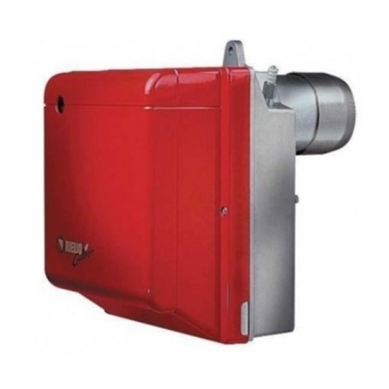
BURNER DESCRIPTION One stage light oil burner. CE Certification No.: 0036 0348/04 as 92/42/EEC. The burner meets protection level of IP XOD (IP 40), EN 60529. Burner with CE marking in conformity with EEC directives: EMC 89/336/EEC, Low Voltage 73/23/EEC, Machines 98/37/EEC and Efficiency 92/42/EEC. -
Page 5: Technical Data
TECHNICAL DATA 2.1 TECHNICAL DATA TYPE 393 T1 − − Output - Thermal power 15 kg/h – 178 kW Fuel Light oil, viscosity 4 – 6 mm /s at 20 °C ± Electrical supply Single phase, 50Hz 230 V Motor Run current 1.9 A –... -
Page 6: Installation
INSTALLATION THE BURNER MUST BE INSTALLED IN CONFORMITY WITH LEGISLATION AND LOCAL STANDARDS. WORKING POSITION The burner is programmed to operate only in positions 1 and 2. Installation 1 is to be preferred since it is the only position where maintenance can be carried out as de- scribed in this manual. -
Page 7: Hydraulic Systems
3.3 HYDRAULIC SYSTEMS Fig. 5 WARNING: The burner is designed to allow installation of the oil- lines on either side of the burner. It is necessary to install a filter on the fuel supply line. The pump is designed for use with a two-pipe system. In order to obtain one-pipe working, it is necessary to unscrew the return plug (2), remove the by-pass screw (3) and then screw the plug (2) up again, (see fig. -
Page 8: Electrical Wiring
3.4 ELECTRICAL WIRING ATTENTION: Do not swap neutral and phase over, follow the diagram shown carefully and carry out a good earth connection. The section of the conductors must be at least 1mm². (Unless requested otherwise by local standards and legislation). The electrical wiring carried out by the installer must be in compliance with the rules in force in the country. -
Page 9: Burner Operation
BURNER OPERATION WARNING QUALIFIED PERSONNEL WITH THE RIGHT INSTRUMENTS MUST HANDLE THE BURNER'S FIRST START-UP COMBUSTION ADJUSTMENT In conformity with Efficiency Directive 92/42/EEC the application of the burner on the boiler, adjustment and testing must be carried out observing the instruction manual of the boiler, including verification of the CO and CO concentration in the flue gases, their temperatures and the average temperature of the water in the boiler. -
Page 10: Maintenance Position
4.5 MAINTENANCE POSITION Fig. 11 To access the nozzle, do the following: Undo the wires (4) from the control box, the flame detector (5) and undo the nut (3) from the pump. Loosen the screws (2) and extract the nozzle holder assembly (1) by turning to the right. -
Page 11: Operating Programme
OPERATING PROGRAMME 4.8.1 NORMAL OPERATION WITH PREHEATING KEY TO LAY-OUT – Flame detector – Ignition transformer LED – Reset button LED indicating operating status MV – Fan motor TL – Limit thermostat V1 – Oil valve Green Yellow Yellow Green + Yellow slow blinking Green + Yellow fast blinking Loss of flame during operation (Recycle max. -
Page 12: Lockout Due To Firing Failure
4.8.2 LOCKOUT DUE TO FIRING FAILURE KEY TO LAY-OUT – Flame detector – Ignition transformer LED – Reset button LED indicating operating status MV – Fan motor TL – Limit thermostat V1 – Oil valve Green+Yellow Green Green + Yellow slow blinking D7360 Green + Yellow fast blinking Green... -
Page 13: Lockout Types And Triggering Times In Case Of Burner Malfunction
COLOUR CODE OF THE CONTROL BOX RESET BUTTON LED Flashing Operating status LED colour codes speed Seconds Standby LED unlit Pre-purging Green Long pre-purging Green Transformer ignition Green + Yellow flashing Fast Regular flame Green + Yellow flashing Slow Post-purging Green + Yellow Recycle Green + Yellow flashing... -
Page 14: Additional Programmable Control Box Functions
ADDITIONAL PROGRAMMABLE CONTROL BOX FUNCTIONS 4.9.1 POST-PURGING FUNCTION (t6) Post-ventilation is a function that maintains air ventilation even after the burner is switched off. The burner switches off when the limit thermostat (TL) opens, cutting off the fuel supply to the valves. To use this function the reset button must be pressed when the limit thermostat is not switched over (burner switched off). -
Page 15: Maintenance
MAINTENANCE Disconnect the electric supply to the burner by switching off the main power switch and close the light oil shut-off valve before maintaining or checking the system. The burner requires scheduled maintenance that must be carried out by qualified personnel and in compliance with local legislation. -
Page 16: Faults / Solutions
SIGNAL PROBABLE CAUSE Loss of flame during operations: 7 pulses – poor burner regulation (insufficient gas); – oil valve faulty or dirty; – flame detector faulty or dirty. Check and monitor oil heater (if fitted): 8 pulses – check the correct position of the bridge socket "P". ATTENTION To reset the control box after the diagnostics display, press the lockout-reset button. -
Page 17: Operating Irregularities
FAULT POSSIBLE CAUSES SOLUTION The ignition electrodes are wrongly Adjust them according to the positioned. instructions of this manual. Burner starts with an Set the air output according to the ignition delay. Air output is too high. instructions of this manual. Nozzle dirty or worn. -
Page 18: Warnings And Safety
WARNINGS AND SAFETY The dimension of the boiler’s combustion chamber must respond to specific values, in order to guarantee a combustion with the lowest polluting emissions rate. You are therefore advised to consult the Technical Assistance Department before choosing this type of burn- er for the combination with a boiler. - Page 20 RIELLO S.p.A. I-37048 San Pietro di Legnago (VR) Tel.: +39.0442.630111 http:// www.rielloburners.com...
Need help?
Do you have a question about the Gulliver RG3 and is the answer not in the manual?
Questions and answers