Table of Contents
Advertisement
Quick Links
INSTALLATION AND OPERATION
SX TRANSISTOR CONTROL
SEPARATELY EXCITED (SX) TRANSISTORIZED DUAL MOTOR TRACTION CONTROLLERS
Note: The information contained herein is intended to assist OEM's, Dealers and Users of electric vehicles in the
application, installation and service of GE solid-state controllers. This manual does not purport to cover all
variations in OEM vehicle types. Nor does it provide for every possible contingency to be met involving vehicle
installation, operation or maintenance. For additional information and/or problem resolution, please refer the matter
to the OEM vehicle manufacturer through his normal field service channels. Do not contact GE directly for this
assistance.
Section 1.0
INTRODUCTION .........................................................................................................................................................4
1.1
1.2
1.3
1.4
Section 2.0
FEATURES OF SX FAMILY OF MOTOR CONTROLLERS .....................................................................................6
2.1
2.1.1
2.1.1.a
2.1.1.b
2.1.1.c
2.1.2
2.1.3
2.1.3.a
2.1.3.b
2.1.4
2.1.4.a
2.1.4.b
2.1.5
2.1.6
2.2
2.2.1
2.2.2
INSTALLATION AND OPERATION MANUAL
(IC3645SR4R333AS2)
Table of Contents
Copyright by General Electric Company May 2000
Motor Characteristics...............................................................................................................4
Solid-State Reversing................................................................................................................5
Flexible System Application .....................................................................................................5
More Features with Fewer Components................................................................................. 5
Performance ..............................................................................................................................6
Oscillator Card Features...................................................................................................6
Standard Operation ...................................................................................................6
Creep Speed ...............................................................................................................6
Control Acceleration ................................................................................................6
Current Limit .......................................................................................................................6
Braking................................................................................................................................6
Regenerative Braking to Zero Speed.......................................................................6
Auto Braking ..............................................................................................................6
Auxiliary Speed Control ....................................................................................................6
Field Weakening ........................................................................................................6
Speed Limits ..............................................................................................................6
Ramp Start..........................................................................................................................7
On-Board Coil Drivers and Internal Coil Suppression .................................................7
System Protective Override......................................................................................................7
Static Return to Off (SRO) ................................................................................................7
Accelerator Volts Hold Off ...............................................................................................7
Page 1
May 2000
Advertisement
Table of Contents
Troubleshooting

Related Manuals for GE IC3645SR4R333AS2


Summary of Contents for GE IC3645SR4R333AS2
- Page 1 OEM vehicle types. Nor does it provide for every possible contingency to be met involving vehicle installation, operation or maintenance. For additional information and/or problem resolution, please refer the matter to the OEM vehicle manufacturer through his normal field service channels. Do not contact GE directly for this assistance.
-
Page 2: Table Of Contents
Suppression ........................14 Recommended Lubrication of Pins and Sockets Prior to Installation ........15 General Troubleshooting Instructions..................15 Traction Controller Status Codes ....................16-30 Section 5.0 SX FAMILY - GE HANDSET INSTRUCTIONS.......................31 General Features ........................31 Purpose/Setup Functions ......................31 Setup Function Procedures .....................32 5.3.1 Setup Mode .......... - Page 3 6.2.3 Connector Reference Numbers..................39 Start-up Display Sequence .....................40 Outline Drawings ........................40 Suggested Wiring Configuration for Use of GE Standard Traction/Pump Dash Display Motor Traction System ......................40 Section 7.0 MEMORY MAPS ................................41 Typical Memory Map for DM Proportioning Control ............41-43...
- Page 4 SPEED advantage of today’s technology, while looking forward to new advances on the horizon. GE has introduced a second generation system using separately excited DC shunt wound motors. The separately excited DC motor system offers many of the features that are generally found on the advanced AC systems.
- Page 5 For GE, the future is now as we make available a new The line can be energized and de-energized by the various generation of electric traction motor systems for electric logic combinations of the vehicle, i.e.
- Page 6 BASIC OPERATION AND FEATURES SX TRANSISTOR CONTROL Page 6 Section 2. FEATURES OF SX FAMILY OF TRANSISTOR current is usually greater than battery current, except at 100% ON time. MOTOR CONTROLLERS Section 2.1.3 Braking Section 2.1 Performance Section 2.1.3.a Regenerative Braking to Zero Speed Section 2.1.1 Oscillator Card Features Slow down is accomplished when Section 2.1.1.a Standard Operation...
-
Page 7: Pulse Monitor Trip (Pmt)
BASIC OPERATION AND FEATURES SX TRANSISTOR CONTROL Page 7 will be determined by GE and OEM engineers at the time of vehicle development. This setting must not be changed by · The control monitors both armature and field FET's at field personnel without the permission of the OEM. -
Page 8: Stored Status Codes
Section 2.3.5 Handset This is a multi-functional tool used with the LX, ZX, and SX Series GE solid state controls. The Handset consists of a Light Emitting Diode (LED) display and a keyboard for data entry. Note, for ordering purposes, a separate Handset part is required for SX controls. -
Page 9: Ordering Information, Elementary And Outline Drawings
OUTLINE DRAWINGS, ELEMENTARY DRAWINGS AND INPUTS/OUTPUTS SX TRANSISTOR CONTROL Page 9 Section 3.0 ORDERING INFORMATION, ELEMENTARY AND OUTLINE DRAWINGS Section 3.1 Ordering Information for Separately Excited Controls Example: Part Number: IC3645 Argument Number: Argument 01: Basic Electric Vehicle Control Number Argument 02: Control Type: Separately Excited Control ( Plugging ) -
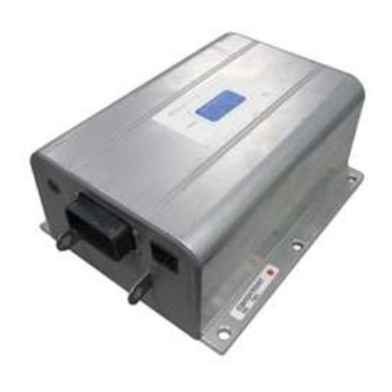
Page 10: Outline: Sx-2 Package Size
OUTLINE DRAWINGS, ELEMENTARY DRAWINGS AND INPUTS/OUTPUTS SX TRANSISTOR CONTROL Page 10 Section 3.2 Outline: SX-2 Package Size May 2000... -
Page 11: Dual Motor Proportioning Drive Elementary
OUTLINE DRAWINGS, ELEMENTARY DRAWINGS AND INPUTS/OUTPUTS SX TRANSISTOR CONTROL Page 11 Section 3.3 Standard Dual Motor Proportioning Drive Elementary May 2000... -
Page 12: Dual Motor Proportioning Drive Input / Output List
OUTLINE DRAWINGS, ELEMENTARY DRAWINGS AND INPUTS/OUTPUTS SX TRANSISTOR CONTROL Page 12 Section 3.4 Standard Dual Motor Proportioning Drive Input/Output List Connections to Main Plug (23 Pin) and “Y” Plug (12 Pin) STANDARD DUAL MOTOR PROPORTIONING MAIN PLUG INPUT/OUTPUT DESCRIPTION BATTERY VOLTS FROM BATTERY 12 VOLTS FROM KEY 12 VOLTS FROM BOOM SWITCH 12 VOLTS FROM DIRECTIONAL SWITCH... -
Page 13: Troubleshooting And Diagnostic Status Codes
STATUS CODE tips are intact and free of contaminants. Section 4.1 General Maintenance Instructions GE does not recommend that any type of welding be The transistor control, like all electrical apparatus, does performed on the vehicle after the installation of the have some thermal losses. -
Page 14: High Level Signals (Level H)
DIAGNOSTIC STATUS CODES SX TRANSISTOR CONTROL Page 14 Section 4.2.3.a General Cable Spacing · All wiring connected to components associated with sensitive analog hardware with less than 5V signals (for example, potentiometers and tachometers) The following general practices should be used for all ·... -
Page 15: Recommended Lubrication Of Pins And Sockets Prior To Installation
EV100/EV200 and Gen II products. Any publication. connection made by GE to the A, B, X, Y, or Z plugs will have the lubricant NYE 760G added to prevent fretting of WARNING: Before trouble-shooting, jack up the drive wheels, disconnect the battery and discharge the these connections during vehicle operation. -
Page 16: Traction Controller Status Codes
DIAGNOSTIC STATUS CODES SX TRANSISTOR CONTROL Page 16 Section 4.5 Traction Control Status Codes TRACTION DESCRIPTION OF STATUS CAUSE OF STATUS INDICATION STATUS CODE Segments do not illuminate on the No input voltage to the control card or the display unit. NONE Dash Display and/or the Handset. - Page 17 DIAGNOSTIC STATUS CODES SX TRANSISTOR CONTROL Page 17 TRACTION DESCRIPTION OF STATUS CAUSE OF STATUS INDICATION STATUS CODE Directional switch is closed on initial This status code will be displayed when P4 is greater power up. than 12% of battery voltage at initial key switch on. MEMORY R CALL CORRECTIVE ACTIONS TROUBLE-SHOOTING DIAGRAM...
- Page 18 DIAGNOSTIC STATUS CODES SX TRANSISTOR CONTROL Page 18 TRACTION DESCRIPTION OF STATUS CAUSE OF STATUS INDICATION STATUS CODE Accelerator depressed without This status code will be displayed when P4 and P5 selecting travel enable switch. are less than 12% of battery volts, and P7 is less than 2.5 volts.
- Page 19 DIAGNOSTIC STATUS CODES SX TRANSISTOR CONTROL Page 19 TRACTION DESCRIPTION OF STATUS CAUSE OF STATUS INDICATION STATUS CODE Accelerator input voltage too low on This status code will be displayed when the power up after initial key switch accelerator input voltage at P7 is less than 3.0 volts, closure.
- Page 20 DIAGNOSTIC STATUS CODES SX TRANSISTOR CONTROL Page 20 TRACTION DESCRIPTION OF STATUS CAUSE OF STATUS INDICATION STATUS CODE Battery voltage is too low or control This status code will be displayed when the battery card is mis-adjusted. volts are less than 1.95 volts per cell at initial key switch on.
- Page 21 DIAGNOSTIC STATUS CODES SX TRANSISTOR CONTROL Page 21 TRACTION DESCRIPTION OF STATUS CAUSE OF STATUS INDICATION STATUS CODE Motor field current is high on start up in This status code will be displayed when the current the reverse direction. draw in the motor field is too high at start up in the reverse direction.
- Page 22 DIAGNOSTIC STATUS CODES SX TRANSISTOR CONTROL Page 22 TRACTION DESCRIPTION OF STATUS CAUSE OF STATUS INDICATION STATUS CODE Power supply is less than 10 Volts DC. This status code will be displayed when the power supply is less than 10 volts. MEMORY RE ALL CORRECTIVE ACTIONS TROUBLE-SHOOTING DIAGRAM...
- Page 23 DIAGNOSTIC STATUS CODES SX TRANSISTOR CONTROL Page 23 TRACTION DESCRIPTION OF STATUS CAUSE OF STATUS INDICATION STATUS CODE Motor armature offset voltage is too This status code will be displayed when the voltage at high. the current sensor input is greater than 2.6 volts with no current flowing in the motor circuit.
- Page 24 DIAGNOSTIC STATUS CODES SX TRANSISTOR CONTROL Page 24 TRACTION DESCRIPTION OF STATUS CAUSE OF STATUS STATUS CODE INDICATION Armature transistor did not turn off properly. This status code will be displayed when, during control operation, the armature transistor fails to turn off. This will result in a PMT condition.
- Page 25 DIAGNOSTIC STATUS CODES SX TRANSISTOR CONTROL Page 25 TRACTION DESCRIPTION OF STATUS CAUSE OF STATUS INDICATION STATUS CODE “Look Ahead” test for A2 volts less This status code will be displayed when the voltage at than 12% of battery volts. A2 is less than 12% of battery volts.
- Page 26 DIAGNOSTIC STATUS CODES SX TRANSISTOR CONTROL Page 26 TRACTION DESCRIPTION OF STATUS CAUSE OF STATUS INDICATION STATUS CODE Motor field current is too low during the This status code will be displayed when the current run mode. draw in the motor field is too low during the run mode. MEMORY R CALL CORRECTIVE ACTIONS TROUBLE-SHOOTING DIAGRAM...
- Page 27 DIAGNOSTIC STATUS CODES SX TRANSISTOR CONTROL Page 27 TRACTION DESCRIPTION OF STATUS CAUSE OF STATUS INDICATION STATUS CODE Controller “motor current sensor” input This status code will be displayed when the voltage too low during running. input from the current sensor is too low during running.
- Page 28 DIAGNOSTIC STATUS CODES SX TRANSISTOR CONTROL Page 28 TRACTION DESCRIPTION OF STATUS CAUSE OF STATUS INDICATION STATUS CODE Motoring fault with capacitor (1C) This status code will be displayed when the voltage voltage too low. on the capacitor is less than 20 volts during motoring. MEMORY RE ALL CORRECTIVE ACTIONS TROUBLE-SHOOTING DIAGRAM...
- Page 29 DIAGNOSTIC STATUS CODES SX TRANSISTOR CONTROL Page 29 TRACTION DESCRIPTION OF STATUS CAUSE OF STATUS INDICATION STATUS CODE Capacitor (1C) voltage too high. This status code will be displayed when the voltage on the capacitor goes above limit voltage* during the regenerative braking cycle.
- Page 30 DIAGNOSTIC STATUS CODES SX TRANSISTOR CONTROL Page 30 TRACTION DESCRIPTION OF STATUS CAUSE OF STATUS INDICATION STATUS CODE The input from the tach sensor has This status code will be displayed when the control is been lost or the motor has stalled. not seeing any tach pulses.
-
Page 31: Sx Family - Ge Handset Instructions
START-UP DISPLAY SEQUENCE Section 5.1 General Features Key Switch On The GE Handset is a multi-functional tool to be used with the LX, ZX, and SX Series GE solid-state controls. The Handset consists of a Light Emitting Diode (LED) display Verify Each LED Segment and a keyboard for data entry. -
Page 32: Setup Function Procedures
NOTE: The term “Push” means to depress key for ACCESSING STORED STATUS CODES approximately one second. WITH GE HANDSET Section 5.3.1 Setup Mode Key Switch Off SET-UP MODE Push ESC and CONT... -
Page 33: Setup Functions For Traction Controller
ADJUSTABLE FEATURES SX TRANSISTOR CONTROLS Page 33 GE and OEM engineers at the time of vehicle development. This setting must not be changed by field personnel without HANDSET the permission of the OEM. FUNCTION 3 ARMATURE CONTROLLED ACCELERATION IN HIGH SPEED MODE... - Page 34 6.28 amps control performance and this setting will be determined by GE and OEM engineers at the time of vehicle development. Important Note: The function is used to optimize motor and This setting must not be changed by field personnel without control performance and this setting will be determined by the permission of the OEM.
- Page 35 No BDI Between 251 and 255 GE and OEM engineers at the time of vehicle development. This setting must not be changed by field personnel without the permission of the OEM.
- Page 36 GE and OEM engineers at the time of vehicle development. This setting must not be changed by field personnel without To determine which stored status code was the last one the permission of the OEM.
- Page 37 ADJUSTABLE FEATURES SX TRANSISTOR CONTROLS Page 37 FUNCTION 48 NOT APPLICABLE FUNCTION 59 NOT APPLICABLE This function is not applicable to this type of control and This function is not applicable to this type of control and should not be adjusted. should not be adjusted.
-
Page 38: Summary Of Current Limit Adjustments
The value for this function will be defined by the GE application engineer. The " minimum field current" setting is adjusted by Function 7. The function sets the top speed of the motor. -
Page 39: Displays
Diagnostics Override Blank Display With Fault (no BDI used) The GE Standard Dash Display is a four segment Light Emitting Diode (LED) instrument that displays the GE LX, ZX, Run Mode and SX Status Codes, Hourmeter Readings, Battery Discharge Indication, and Maintenance Required Code. -
Page 40: Outline Drawings
INSTALLATION AND OPERATION MANUAL SX TRANSISTOR CONTROL Page 40 Section 6.4 Outline Drawings Section 6.5 Suggested Wiring Configuration for Use of GE For the standard GE traction dash display: Standard Traction/Pump Dash Display with Dual Motor Traction System NOTE: USE SHIELDED... -
Page 41: Memory Maps
Error Compensation HS or PC None FW Start HS or PC None Monitor HS or PC GE Temporary Storage Ratio HS or PC GE Temporary Storage Not Used HS or PC GE Temporary Storage Stored Status Code Count Pointer HS or PC... - Page 42 RS-232 MEMORY MAP TABLES SX TRANSISTOR CONTROL Page 42 Func No. Traction Control Access By Restrictions Function BDI 4 PC Only Reset to Zero Only Hours (Tens/Ones) 4 PC Only Reset to Zero Only Hours (Thou/Hun) 4 PC Only Reset to Zero Only (26) Stored Status Code #5 PC Only...
- Page 43 OEM Read Only Secure Aux HM (Tens/Ones) PC Only OEM Read Only Secure Aux HM (Thou/Hun) PC Only OEM Read Only Reserved PC Only GE Future Use Reserved PC Only GE Future Use Reserved PC Only GE Future Use Reserved PC Only...
Need help?
Do you have a question about the IC3645SR4R333AS2 and is the answer not in the manual?
Questions and answers