Table of Contents
Advertisement
Quick Links
INSTALLATION AND OPERATION
SX TRANSISTOR CONTROL
SEPARATELY EXCITED (SX) TRANSISTORIZED MOTOR CONTROLLERS
Note: The information contained herein is intended to assist OEM's, Dealers and Users of electric vehicles in the application,
installation and service of GE solid-state controllers. This manual does not purport to cover all variations in OEM vehicle types.
Nor does it provide for every possible contingency to be met involving vehicle installation, operation or maintenance. For
additional information and/or problem resolution, please refer the matter to the OEM vehicle manufacturer through his normal
field service channels. Do not contact GE directly for this assistance.
Section 1.0
INTRODUCTION .................................................................................................................................................... 3
1.1
1.2
1.3
1.4
Section 2.0
FEATURES OF SX FAMILY OF MOTOR CONTROLLERS .................................................................................. 4
2.1
2.1.1
2.1.2
2.1.3
2.1.4
2.1.5
2.1.5.b
FOR NEIGHBORHOOD ELECTRIC VEHICLE APPLICATION
INSTALLATION AND OPERATION MANUAL
(GE MODEL IC3645SH4V262Y1)
General Electric Company June 2002
Motor Characteristics ................................................................................................................. 3
Solid-State Reversing .................................................................................................................. 4
Flexible System Application........................................................................................................ 4
More Features with Fewer Components .................................................................................. 4
Performance.................................................................................................................................. 4
Oscillator Card Features...................................................................................................................... 4
Standard Operation.............................................................................................................. 4
Control Acceleration ........................................................................................................... 5
Regenerative Braking to Base Speed ............................................................................................... 5
Auxiliary Speed Control....................................................................................................................... 5
Field Weakening ................................................................................................................... 5
Speed Limits ......................................................................................................................... 5
Top Speed Regulation.......................................................................................................... 5
Table of Contents
Page 1
June 2002
Advertisement
Table of Contents
Troubleshooting

Related Manuals for GE H4V262Y1


Summary of Contents for GE H4V262Y1
-
Page 1: Table Of Contents
Note: The information contained herein is intended to assist OEM's, Dealers and Users of electric vehicles in the application, installation and service of GE solid-state controllers. This manual does not purport to cover all variations in OEM vehicle types. Nor does it provide for every possible contingency to be met involving vehicle installation, operation or maintenance. For additional information and/or problem resolution, please refer the matter to the OEM vehicle manufacturer through his normal field service channels. - Page 2 INSTALLATION AND OPERATION Table of Contents ( Continued ) SX TRANSISTOR CONTROL Page 2 2.1.6 Ramp Start 5 2.1.7 On-Board Coil Drivers and Internal Coil Suppression ..............5 System Protective Override ......................6 2.2.1 Static Return to Off (SRO) ........................6 2.2.2 Accelerator Volts Hold Off ........................
-
Page 3: Introduction
SPEED new advances on the horizon. GE has introduced a second generation system using separately excited DC shunt wound motors. The separately excited DC motor system offers many of the features that are generally found on the advanced AC systems. -
Page 4: Solid-State Reversing
By energizing the transistors in pairs, current can be made to flow in either direction in the field. The field and For GE, the future is now, as we make available a new armature control circuits typically operate at 15KHZ, a generation of electric traction motor systems for electric frequency range normally above human hearing. -
Page 5: Control Acceleration
This feature requires a system tachometer. The standard oscillator and limits the average current to a value set by GE system tach is built into the motor and provides four Function 4 and Function 8 of the Handset. The C/L setting is pulses per armature revolution. -
Page 6: System Protective Override
If mis-operation of the vehicle occurs, a status code will be displayed on the lap top personal low speed operation at start up. computer, using GE Sentry for Windows software, or on the Section 2.2.3 Pulse Monitor Trip (PMT) PDA handset. - Page 7 BASIC OPERATION AND FEATURES SX TRANSISTOR CONTROL Page 7 from the control card, these drivers initiate opening and connected incorrectly, the contactors can not be closed closing the contactor coils. All driver modules are equipped electrically. with reverse battery protection, such that, if the battery is June 2002...
-
Page 8: Ordering Information, Elementary And Outline Drawings
OUTLINE DRAWINGS, ELEMENTARY DRAWINGS AND INPUTS/OUTPUTS SX TRANSISTOR CONTROL Page 8 Section 3.0 ORDERING INFORMATION, ELEMENTARY AND OUTLINE DRAWINGS Section 3.1 Ordering Information for Separately Excited Controls Example: Part Number: IC3645 Argument Number: Argument 01: Basic Electric Vehicle Control Number Argument 02: Control Type: Separately Excited Control ( Plugging ) -
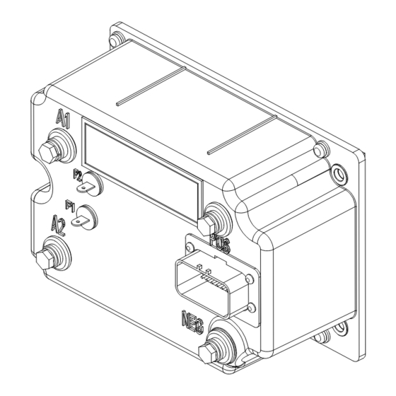
Page 9: Outline: Gen Iv Package Size
OUTLINE DRAWINGS, ELEMENTARY DRAWINGS AND INPUTS/OUTPUTS SX TRANSISTOR CONTROL Page 9 Section 3.2 Outline: Gen IV Package Size June 2002... -
Page 10: Standard Elementary For Golf Car Application
OUTLINE DRAWINGS, ELEMENTARY DRAWINGS AND INPUTS/OUTPUTS SX TRANSISTOR CONTROL Page 10 Section 3.3 Standard Elementary for Golf Car Application June 2002... -
Page 11: Golf Car Application Input/Output List
OUTLINE DRAWINGS, ELEMENTARY DRAWINGS AND INPUTS/OUTPUTS SX TRANSISTOR CONTROL Page 11 Section 3.4 Golf Car Application Input/Output List June 2002... - Page 12 OUTLINE DRAWINGS, ELEMENTARY DRAWINGS AND INPUTS/OUTPUTS SX TRANSISTOR CONTROL Page 12 Connections to Main Plug (23 Pin) MAIN PLUG INPUT/OUTPUT DESCRIPTION BATTERY VOLTS FROM TOW SWITCH BATTERY VOLTS FROM TOW SWITCH BATTERY VOLTS FROM ACCELERATOR START SWITCH BATTERY VOLTS FROM FORWARD SWITCH BATTERY VOLTS FROM REVERSE SWITCH BATTERY VOLTS FROM KEY SWITCH ACCELERATOR INPUT VOLTAGE SIGNAL...
-
Page 13: Troubleshooting And Diagnostic Status Codes
The semiconductor junctions have finite temperature limits, above which these devices GE does not recommend that any type of welding be may be damaged. For these reasons, normal maintenance performed on the vehicle after the installation of the should guard against any action which will expose the control(s) in the vehicle. -
Page 14: High Level Signals (Level H)
DIAGNOSTIC STATUS CODES SX TRANSISTOR CONTROL Page 27 • Control common tie customer must apply the general guidelines (section 4.2.3.a), outlined below. • DC buses feeding sensitive analog or digital hardware • All wiring connected to components associated with 4.2.3.a General Cable Spacing sensitive analog hardware with less than 5V signals (for example, potentiometers and tachometers) •... -
Page 15: Recommended Lubrication Of Pins And Sockets Prior To Installation
EV100/EV200 and Gen II products. Any connection made by WARNING: Before conducting maintenance on the GE to the A, B, X, Y, or Z plugs, includes the lubricant NYE vehicle, jack up the drive wheels, disconnect the battery 760G to prevent fretting of these connections during vehicle and discharge the operation. -
Page 16: General Troubleshooting Instructions
Lubricant Nye Lubricants NYOGEL 760G wiring diagrams for a specific vehicle, but these numbers GE Plug Lub Kit Contains both above products: may be different from the numbers referenced in this 328A1777G1 publication. - Page 17 DIAGNOSTIC STATUS CODES SX TRANSISTOR CONTROL Page 17 Section 4.5 Traction Control Codes TRACTION DESCRIPTION OF STATUS CAUSE OF STATUS INDICATION STATUS CODE Segments do not illuminate on the No input voltage to the control card or the display NONE Dash Display and/or the Handset.
- Page 18 DIAGNOSTIC STATUS CODES SX TRANSISTOR CONTROL Page 18 TRACTION DESCRIPTION OF STATUS CAUSE OF STATUS INDICATION STATUS CODE The accelerator pedal is depressed with This status code will be displayed when the no direction selected. accelerator voltage, at P7>1.4V, and no direction is selected (P4 and P5 are both less than 50% of battery volts) MEMORY RECALL...
- Page 19 DIAGNOSTIC STATUS CODES SX TRANSISTOR CONTROL Page 19 TRACTION DESCRIPTION OF STATUS CAUSE OF STATUS INDICATION STATUS CODE Both the forward and reverse switches are This status code will be displayed when P4 and closed at the same time. P5 are greater than 50% of battery volts. MEMORY RECALL CORRECTIVE ACTIONS TROUBLE-SHOOTING DIAGRAM...
- Page 20 DIAGNOSTIC STATUS CODES SX TRANSISTOR CONTROL Page 20 TRACTION DESCRIPTION OF STATUS CAUSE OF STATUS INDICATION STATUS CODE Battery voltage is too low at initial key This status code will be displayed when the switch closure. battery volts are less than 68.3 volts at initial key switch on.
- Page 21 DIAGNOSTIC STATUS CODES SX TRANSISTOR CONTROL Page 21 TRACTION DESCRIPTION OF STATUS CAUSE OF STATUS INDICATION STATUS CODE Accelerator voltage is too high. This status code will be displayed when the accelerator voltage at P7 is greater than 4.5 volts. MEMORY RECALL CORRECTIVE ACTIONS TROUBLE-SHOOTING DIAGRAM...
- Page 22 DIAGNOSTIC STATUS CODES SX TRANSISTOR CONTROL Page 22 TRACTION DESCRIPTION OF STATUS CAUSE OF STATUS INDICATION STATUS CODE Motor field current is too high on when This status code will be displayed when the current the key switch is turned on. draw in the motor field is too high on start up.
- Page 23 (Values of less than 1 V at the thermal protector are typically indicative of a failed control.) GE Sentry for Windows software can be used to monitor control operation, and it will display a value for the thermal protector that is greater than 84 (corresponding to 1.65V), triggering this status code.
- Page 24 Traction Defective control. Controller • Replace controller unit. GE Sentry for Windows software can be used to monitor control operation, and it will display a value for the motor amps that is less than 117 (corresponding to 2.3V), triggering this status code.
- Page 25 DIAGNOSTIC STATUS CODES SX TRANSISTOR CONTROL Page 25 TRACTION DESCRIPTION OF STATUS CAUSE OF STATUS INDICATION STATUS CODE Armature transistor did not turn on This status code will be displayed when, during properly. control operation, the armature transistor fails to turn on properly.
- Page 26 DIAGNOSTIC STATUS CODES SX TRANSISTOR CONTROL Page 26 TRACTION DESCRIPTION OF STATUS CAUSE OF STATUS INDICATION STATUS CODE Motor field current is too low during the This status code will be displayed when the current run mode. draw in the motor field is less than 1.3 amps and armature current is greater than 100 amps for more than 1.27 seconds during the run mode.
- Page 27 DIAGNOSTIC STATUS CODES SX TRANSISTOR CONTROL Page 27 TRACTION DESCRIPTION OF STATUS CAUSE OF STATUS INDICATION STATUS CODE Controller “motor current sensor” input This status code will be displayed when the voltage is too low during running. input from the current sensor is too low (less than 1.0V, 416 amps) during running.
- Page 28 DIAGNOSTIC STATUS CODES SX TRANSISTOR CONTROL Page 28 TRACTION DESCRIPTION OF STATUS CAUSE OF STATUS INDICATION STATUS CODE This status code will be displayed MEMORY RECALL CORRECTIVE ACTIONS TROUBLE-SHOOTING DIAGRAM SYMPTOM Control will not operate. Circuits valid FU3 * POSSIBLE CAUSES Traction Line contactor coil is shorted.
- Page 29 DIAGNOSTIC STATUS CODES SX TRANSISTOR CONTROL Page 29 TRACTION DESCRIPTION OF STATUS CAUSE OF STATUS INDICATION STATUS CODE Capacitor (1C) voltage too high during This status code will be displayed when the voltage at pedal up regen braking. 1C exceeds 79 volts during the regenerative braking cycle.
- Page 30 Important Note: The function is used to optimize motor and control performance and this setting will be determined by GE and OEM engineers at the time of vehicle development. This setting must not be changed by field personnel without the permission of the OEM.
- Page 31 = 3.3 amps control performance and this setting will be determined by GE and OEM engineers at the time of vehicle development. CAUTION: Do not set this function to a value less than 51. This setting must not be changed by field personnel without the permission of the OEM.
- Page 32 Mode 0 is selected. INTERNAL RESISTANCE COMPENSATION TABLE Important Note: The function is used to optimize motor and control performance and this setting will be determined by GE and OEM engineers at the time of vehicle development. Setting Setting Drop Drop This setting must not be changed by field personnel without 11.44...
- Page 33 0 to 60 minutes control performance and this setting will be determined by Resolution 0.5 minutes per set unit GE and OEM engineers at the time of vehicle development. Setting 0 to 120 This setting must not be changed by field personnel without Example Setting of 60 = 60 x 0.5 = 30 minutes...
- Page 34 ADJUSTABLE FEATURES SX TRANSISTOR CONTROLS Page 33 0 to 9 0 to 99 Example 999999.9 Miles or Kilometers Example 999999.9 Miles or Kilometers FUNCTION 49 ODOMETER TENS AND UNITS OF MILES OR KILOMETERS SET FUNCTION 51 ODOMETER HUNDRED THOUSANDS AND TEN THOUSANDS OF MILES OR KILOMETERS SET This function allows for the adjustment of the tens and units of miles or kilometers on the odometer.
-
Page 35: Summary Of Current Limit Adjustments
The value for this function will be defined by the GE application engineer. The " minimum field current" setting is adjusted by Function 7. The function sets the top speed of the motor. -
Page 36: Memory Map
Error Compensation PC Only None Field Weakening Start (or Motor Knee Point) PC Only None Monitor PC Only GE Temporary Storage Ratio of Field to Armature Amps PC Only None Hour Meter Minutes PC Only None Stored Status Code Count Pointer... - Page 37 RS-232 MEMORY MAP TABLES SX TRANSISTOR CONTROL Page 41 Stored Status Code #4 PC Only Reset to Zero Only Func No. Traction Control Access By Restrictions Function BDI 4 PC Only Reset to Zero Only Hours (Tens/Ones) 4 PC Only Reset to Zero Only Hours (Thou/Hun) 4 PC Only...
- Page 38 OEM Read Only Secure Aux HM (Tens/Ones) PC Only OEM Read Only Secure Aux HM (Thou/Hun) PC Only OEM Read Only Reserved PC Only GE Future Use Reserved PC Only GE Future Use Reserved PC Only GE Future Use Reserved PC Only...
Need help?
Do you have a question about the H4V262Y1 and is the answer not in the manual?
Questions and answers