
Related Manuals for Baumer MHGP 200


Summary of Contents for Baumer MHGP 200
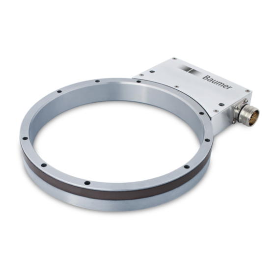
- Page 1 Montage- und Betriebsanleitung Mounting and operating instructions MHGP 200 - HDmag Lagerloser Drehgeber - inkremental Magnetische Abtastung Encoder without bearings - incremental Magnetic sensing...
-
Page 2: Table Of Contents
Heißschrumpfmontage (MHGP 200 B5 G) ................4.1.4 Klemmringmontage (MHGP 200 B5 K) ..................Montage des Abtastkopfes ........................Abmessungen ................................Schraubmontage oder Heißschrumpfmontage (MHGP 200 B5 G) ........Spannsatzmontage (MHGP 200 B5 Z) .................... Klemmringmontage (MHGP 200 B5 K) ................... Elektrischer Anschluss ............................Anschluss Rundsteckverbinder ...................... - Page 3 Mounting ................................... Mounting the encoder wheel ........................4.1.1 Screw mounting (MHGP 200 B5 G) ....................4.1.2 Clamping set mounting (MHGP 200 B5 Z) ..................4.1.3 Shrink fit mounting (MHGP 200 B5 G) ..................4.1.4 Clamping ring mounting (MHGP 200 B5 K) ................Mounting the sensor head ........................
-
Page 4: Allgemeine Hinweise
Hinweis zur Gewährleistung eines einwandfreien Betriebes des Gerätes Information Empfehlung für die Gerätehandhabung Der lagerlose Drehgeber MHGP 200 ... ist ein Prä zi sionsmessgerät, das mit Sorgfalt nur von technisch qualifiziertem Per sonal gehandhabt werden darf. Der Lagertemperaturbereich des Gerätes liegt zwischen -15 °C bis +70 °C. -
Page 5: General Notes
Information Recommendation for device handling The encoder without bearings MHGP 200 ... is a precision measurement device which must be handled with care by skilled personnel only. The storage temperature range of the device is between -15 °C and +70 °C. -
Page 6: Sicherheitshinweise
Montage / Mounting Sicherheitshinweise Sicherheitshinweise Verletzungsgefahr durch rotierende Wellen Haare und Kleidungsstücke können von rotierenden Wellen erfasst werden. • Vor allen Arbeiten alle Betriebsspannungen ausschalten und Maschinen stillsetzen. Zerstörungsgefahr durch mechanische Überlastung • Gerät nie senkrecht - das heißt auf das Magnetband - stellen. •... -
Page 7: Security Indications
Montage / Mounting Security indications Security indications Risk of injury due to rotating shafts Hair and clothes may become tangled in rotating shafts. • Before all work switch off all voltage supplies and ensure machinery is stationary. Risk of destruction due to mechanical overload •... -
Page 8: Vorbereitung
Geberrad je nach Version 3.1.1 Encoder wheel depending on version Geberrad für Schraubmontage oder Heiß- Encoder wheel for screw mounting or schrumpfmontage shrink fit mounting (MHGP 200 B5 G) (MHGP 200 B5 G) Inkrementalspur Incremental track Nullimpulsspur Zero pulse track Nullimpulsmarkierung Zero pulse marker 6x Befestigungsbohrung ø5,5 mm... - Page 9 Montage / Mounting 3.1.1 Geberrad je nach Version 3.1.1 Encoder wheel depending on version Geberrad für Klemmringmontage Encoder wheel for clamping ring mounting (MHGP 200 B5 K) (MHGP 200 B5 K) Inkrementalspur Incremental track Nullimpulsspur Zero pulse track Nullimpulsmarkierung Zero pulse marker...
-
Page 10: Abtastkopf
Montage / Mounting Vorbereitung / Preparation Lieferumfang Scope of delivery 3.1.2 Abtastkopf 3.1.2 Sensor head Abtastkopf mit FPGA-Signalverarbeitung Sensor head with FPGA signal processing Zyl. Bohrung für M6, ISO 4762 Cyl. bore for M6, ISO 4762 Flanschdose M23, 12-polig, Stiftkontakte, Flange connector M23, 12-pin, male, CCW, linksdrehend, siehe Abschnitt 6.3. -
Page 11: Zur Demontage Erforderlich (Nicht Im Lieferumfang Enthalten)
Vorbereitung / Preparation Montage / Mounting Zur Demontage erforderlich Required for dismounting (nicht im Lieferumfang enthalten) (not included in scope of delivery) Abdrückschraube ISO 4762, M5x20 mm bei Jack screw ISO 4762, M5x20 mm Geberrad für Schraubmontage oder Heiß- for encoder wheel for screw mounting or schrumpfmontage, shrink fit mounting, siehe 1 in Abschnitt 3.1.1. -
Page 12: Montage
Montage / Mounting Montage Mounting Montage des Geberrades Mounting the encoder wheel 4.1.1 Schraubmontage 4.1.1 Screw mounting (MHGP 200 B5 G) (MHGP 200 B5 G) 4 mm Zul. Anzugsmoment: Max. tightening torque: = 3...4 Nm øA , øC = 50...180 mm Antriebswelle einfetten. -
Page 13: Heißschrumpfmontage (Mhgp 200 B5 G)
Montage des Geberrades Mounting the encoder wheel 4.1.3 Heißschrumpfmontage 4.1.3 Shrink fit mounting (MHGP 200 B5 G) (MHGP 200 B5 G) Das Geberrad auf +40...+120 °C Warm up the encoder wheel to erwärmen. +40...+120 °C. = T - (≥20 °C) T = +40...+120 °C... -
Page 14: Montage Des Abtastkopfes
Montage / Mounting Montage des Abtastkopfes Mounting the sensor head Geberrad Encoder wheel Befestigungsmöglichkeit für den Abtastkopf (Beispiel). Fixing element for the sensor head (example). Zul. Anzugsmoment: Max. tightening torque: = 3...4 Nm Typenschild Type label 5 mm ±3 mm Zulässiger Axialversatz zwischen Abtastkopf und Geberrad Permissible axial displacement... -
Page 15: Abmessungen
Abmessungen / Dimensions Montage / Mounting Abmessungen Dimensions Schraubmontage oder Heißschrumpf- Screw mounting or shrink fit mounting montage (MHGP 200 B5 G) (MHGP 200 B5 G) 3x Abdrückgewinde M5 3x Jack-screw thread M5 Nicht vorhanden wenn øA =180 Not present if øA =180 6x ø5.5... -
Page 16: Klemmringmontage (Mhgp 200 B5 K)
Montage / Mounting Abmessungen / Dimensions Klemmringmontage Clamping ring mounting (MHGP 200 B5 K) (MHGP 200 B5 K) (øA <80 = 42) Drehrichtung positiv Positive rotating direction øA = 70...150 Nullimpulsmarkierung Zero pulse marker Luftspalt Air gap Alle Abmessungen in Millimeter (wenn nicht anders angegeben) -
Page 17: Elektrischer Anschluss
Elektrischer Anschluss / Electrical connection Montage / Mounting Elektrischer Anschluss Electrical connection Anschluss Rundsteckverbinder Connecting mating connector 6.1.1 Schritt 1 6.1.1 Step 1 Ansicht X Löteinsatz, Belegung siehe Abschnitt 6.3. ø7...12 mm View X Insert with solder contacts, Kabelschirm assignment see section 6.3. Cable shield Ansicht X View X... -
Page 18: Beschreibung Der Anschlüsse
Montage / Mounting Elektrischer Anschluss / Electrical connection Anschluss Rundsteckverbinder Connecting mating connector 6.1.2 Schritt 2 6.1.2 Step 2 Handfest Hand-tight Ansicht Y siehe Abschnitt 6.3. View Y * Siehe Seite 7 see section 6.3. See page 7 Beschreibung der Anschlüsse Terminal significance Betriebsspannung +UB;... -
Page 19: Stiftbelegung Flanschdose
Elektrischer Anschluss / Electrical connection Montage / Mounting Stiftbelegung Flanschdose Pin assignment flange connector Ansicht Y in Flanschdose, Stiftbelegung Flanschdose M23, 12-polig, siehe Abschnitt 6.1.2. Stiftkontakte, linksdrehend. View Y in flange connector, Pin assignment flange connector M23, 12-pin, see section 6.1.2. male, CCW. B− 10 12 R− A− Benutzung des Stifts kann zur Beschädigung des Gerätes führen Use of the pin can damage the device Betriebsspannung nicht auf Ausgänge... -
Page 20: Sensorkabel Hek 8 (Zubehör)
360°el. Sensorkabel HEK 8 (Zubehör) Sensor cable HEK 8 (accessory) Es wird empfohlen, das Baumer Hübner Baumer Hübner sensor cable HEK 8 is Sensorkabel HEK 8 zu verwenden oder recommended. As a substitute a shielded ersatzweise ein geschirmtes, paarig ver- twisted pair cable should be used. -
Page 21: Demontage
Demontage / Dismounting Montage / Mounting Demontage Dismounting Demontage des Abtastkopfes Dismounting the sensor head 5 mm 4.1 * * Siehe Seite 7 oder 8 See page 7 or 8 MB211T1 - 11105827 Baumer_MHGP200-T1_II_DE-EN (19A2) -
Page 22: Demontage Des Geberrades
Montage / Mounting Demontage / Dismounting Demontage des Geberrades Dismounting the encoder wheel 7.2.1 Schraubmontage 7.2.1 Screw mounting (MHGP 200 B5 G) (MHGP 200 B5 G) 4 mm 4 mm 7.2.2 Spannsatzmontage 7.2.2 Clamping set mounting (MHGP 200 B5 Z) -
Page 23: Heißschrumpfmontage (Mhgp 200 B5 G)
Demontage / Dismounting Montage / Mounting Demontage des Geberrades Dismounting the encoder wheel 7.2.3 Heißschrumpfmontage 7.2.3 Shrink fit mounting (MHGP 200 B5 G) (MHGP 200 B5 G) 4 mm 7.2.4 Klemmringmontage 7.2.4 Clamping ring mounting (MHGP 200 B5 K) (MHGP 200 B5 K) -
Page 24: Technische Daten
Montage / Mounting Technische Daten Technische Daten Technische Daten - elektrisch • Störfestigkeit: EN 61000-6-2 • Störaussendung: EN 61000-6-3 • Zulassungen: UL-Zulassung / E217823 Technische Daten - elektrisch (Rechteck) • Betriebsspannung (Signale): RN...C: 4,5...30 VDC (TTL/RS422) TN...C: 5 VDC ±5 % (TTL/RS422) HN...C: 10...30 VDC... -
Page 25: Technische Daten - Mechanisch
Montage / Mounting Technische Daten - mechanisch • Abtastkopf: FPGA-Signalverarbeitung • Baugröße (Flansch): ø201,7 mm • Wellenart: ø50...180 mm (durchgehende Hohlwelle) (je nach Bestellung) • Axiale Toleranz: ±3 mm (Rad/Kopf) • Radiale Toleranz: 0,1...2,2 mm (Rad/Kopf) • Schutzart DIN EN 60529: IP67 (Kopf) IP68 (Rad) •... -
Page 26: Technical Data
Montage / Mounting Technical data Technical data Technical data - electrical ratings • Interference immunity: EN 61000-6-2 • Emitted interference: EN 61000-6-3 • Approvals: UL approval / E217823 Technical data - electrical ratings (square-wave) • Voltage supply (Signals): RN...C: 4.5...30 VDC (TTL/RS422) TN...C: 5 VDC ±5 %... -
Page 27: Technical Data - Mechanical Design
Montage / Mounting Technical data - mechanical design • Sensor head: FPGA signal processing • Size (flange): ø201.7 mm • Shaft type: ø50...180 mm (through hollow shaft) (as ordered) • Axial tolerance: ±3 mm (wheel/head) • Radial tolerance: 0.1...2.2 mm (wheel/head) • Protection DIN EN 60529: IP67 (head) IP68 (wheel) •... -
Page 28: Zubehör
• Various interpolators/splitters/ Vervielfacher auf Anfrage multipliers on request * Siehe Abschnitt 3 See section 3 Baumer Hübner GmbH P.O. Box 12 69 43 · 10609 Berlin, Germany Phone: +49 (0)30/69003-0 · Fax: +49 (0)30/69003-104 info@baumerhuebner.com · www.baumer.com/motion MB211T1 - 11105827...
Need help?
Do you have a question about the MHGP 200 and is the answer not in the manual?
Questions and answers