Advertisement
Quick Links
DESCRIPTION
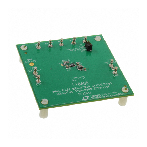
Demonstration Circuit 2564A is a 42V, 0.35A micropower
synchronous step-down regulator featuring the
The demo board is designed for 5V output from a 5.5V
to 42V input. The wide input range allows a variety of
input sources, such as automotive batteries and indus-
trial supplies. The LT8606 is a compact, high efficiency,
high speed synchronous monolithic step-down switch-
ing regulator that consumes less than 3μA of quiescent
current when output is regulated at 5V. Top and bottom
power switches, compensation components and other
necessary circuits are inside of the LT8606 to minimize
external components and simplify design.
The SYNC pin on the demo board is grounded by default
for low ripple Burst Mode
SKIPPING position can change the operation mode to
pulse-skipping operation. Once JP1 is on SPREAD SPEC-
TRUM position, VCC is applied to the SYNC pin for low
EMI spread spectrum operation. To synchronous to an
external clock, move JP1 to SYNC and apply the external
PERFORMANCE SUMMARY
SYMBOL
PARAMETER
V
Input Voltage Range
IN
V
Output Voltage
OUT
I
Maximum Output Current
OUT
f
Switching Frequency
SW
EFE
Efficiency at DC
Arrow.com.
Downloaded from
42V, 0.35A Micropower Synchronous
LT
®
operation. Move JP1 to PULSE
®
Specifications are at T
CONDITIONS
V
IN
DEMO MANUAL DC2564A
Step-Down Regulator
clock to the SYNC turret. Figure 1 shows the efficiency
8606.
of the circuit.
The demo board has an EMI filter installed. The radiated
EMI performances of the board (with EMI filter) are shown
in Figures 2 and 3. The red/green lines in Figures 2 and
3 are CISPR25 Class 5 peak/average limit. To use the
EMI filter, the input should be tied to VEMI, not VIN. An
inductor L2, which is a 0Ω jumper on the board by default
now, can be added in the EMI filter to further reduce the
conducted emission.
The LT8606 data sheet gives a complete description of
the part, operation and application information. The data
sheet must be read in conjunction with this demo manual
for DC2564A.
Design files for this circuit board are available at
http://www.linear.com/demo/DC2564A
L, LT, LTC, LTM, Linear Technology, the Linear logo and Burst Mode are registered trademarks
of Analog Devices, Inc. All other trademarks are the property of their respective owners.
= 25°C
A
= 12V, I
= 0.35A
OUT
LT8606
MIN
TYP
MAX
UNITS
5.5
42
4.8
5
5.2
0.35
1.85
2
2.15
92.1
dc2564af
1
V
V
A
MHz
%
Advertisement

Related Manuals for Linear Technology Analog Devices DC2564A


Summary of Contents for Linear Technology Analog Devices DC2564A
- Page 1 TRUM position, VCC is applied to the SYNC pin for low EMI spread spectrum operation. To synchronous to an L, LT, LTC, LTM, Linear Technology, the Linear logo and Burst Mode are registered trademarks of Analog Devices, Inc. All other trademarks are the property of their respective owners.
- Page 2 DEMO MANUAL DC2564A QUICK START PROCEDURE DC2564A is easy to set up to evaluate the performance a. If efficiency measurements are desired, an ammeter of the LT8606. Refer to Figure 4 for proper measurement can be put in series with the output load in order equipment setup and follow the procedure below: to measure the DC2564A’s output current.
- Page 3 DEMO MANUAL DC2564A QUICK START PROCEDURE Figure 2. LT8606 Demo Circuit EMI Performance in CISPR25 Radiated Emission Test, Antenna Polarization: Vertical, Peak Detector (V = 14V, V = 5V, I = 0.35A, 2MHz Switching Frequency) dc2564af Arrow.com. Arrow.com. Arrow.com. Downloaded from Downloaded from Downloaded from...
- Page 4 DEMO MANUAL DC2564A QUICK START PROCEDURE Figure 3. LT8606 Demo Circuit EMI Performance in CISPR25 Radiated Emission Test, Antenna Polarization: Vertical, Average Detector (V = 14V, V = 5V, I = 0.35A, 2MHz Switching Frequency) dc2564af Arrow.com. Arrow.com. Arrow.com. Arrow.com. Downloaded from Downloaded from Downloaded from...
- Page 5 DEMO MANUAL DC2564A QUICK START PROCEDURE Figure 4. Proper Measurement Equipment Setup Figure 5. Measuring Output Ripple dc2564af Arrow.com. Arrow.com. Arrow.com. Arrow.com. Arrow.com. Downloaded from Downloaded from Downloaded from Downloaded from Downloaded from...
-
Page 6: Parts List
DEMO MANUAL DC2564A PARTS LIST ITEM REFERENCE PART DESCRIPTION MANUFACTURER/PART NUMBER Required Circuit Components CAP ., X7R, 1µF, 50V, 10% 0805 MURATA, GRM21BR71H105KA12L CAP ., X7R, 0.22µF, 16V, 10%, 0603 MURATA, GRM188R71C224KA01D CAP ., C0G, 10pF, 25V, 5%, 0603 AVX, 06033A100JAT2A CAP ., X7R, 10µF, 10V, 10%, 0805 MURATA, GRM21BR71A106KE51K CAP ., X7R, 1µF, 25V, 10%, 0603... -
Page 7: Schematic Diagram
Information furnished by Linear Technology Corporation is believed to be accurate and reliable. However, no responsibility is assumed for its use. Linear Technology Corporation makes no representa- tion that the interconnection of its circuits as described herein will not infringe on existing patent rights. - Page 8 Linear Technology Corporation (LTC) provides the enclosed product(s) under the following AS IS conditions: This demonstration board (DEMO BOARD) kit being sold or provided by Linear Technology is intended for use for ENGINEERING DEVELOPMENT OR EVALUATION PURPOSES ONLY and is not provided by LTC for commercial use. As such, the DEMO BOARD herein may not be complete in terms of required design-, marketing-, and/or manufacturing-related protective considerations, including but not limited to product safety measures typically found in finished commercial goods.
Need help?
Do you have a question about the Analog Devices DC2564A and is the answer not in the manual?
Questions and answers