Advertisement
Quick Links
Description
Demonstration circuit 2181 is an
stration board. The DC2181 is used with the DC1968A
wireless power transmitter or the PowerByProxi ProxiPoint
transmitter (both available separately). Either can deliver
2W to the DC2181, with up to 10mm spacing between
the transmitter and the receive coil. The basic transmitter
doesn't support foreign metal object detection. Transmitters
available separately. See last page for details.
performance summary
SYMBOL
PARAMETER
HVIN
DC1968A High Voltage Input Voltage Range
V
DC1968A V
CC
V(BAT)
DC2181A BAT Pin Voltage
I(BAT)
DC2181A BAT Pin Current
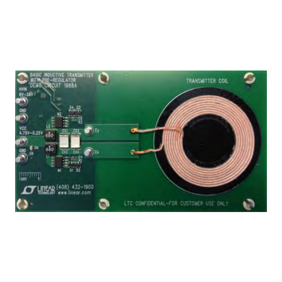
BoarD photo
Figure 2. DC1968A Wireless Power Basic Transmitter Demo Board
Arrow.com.
Downloaded from
LTC
4120EUD
®
Input Range
CC
OR
Figure 1. DC2181 Wireless Power Receiver Demo Board
Wireless Power Receiver
and 400mA Buck Battery Charger
demon-
DC2181A-A
DC2181A-B
Design files for this circuit board are available at
http://www.linear.com/demo/DC2181A
L, LT, LTC, LTM, Linear Technology and the Linear logo are registered trademarks of Linear
Technology Corporation. All other trademarks are the property of their respective owners.
Specifications are at T
= 25°C
A
CONDITIONS
IHVIN ≤ 500mA at HVIN = 8V
IV
= 0 ~ 700mA
CC
R9 = 1.40MΩ, R10 = 1.05MΩ
V(BAT) = 3.7V, DC1967A(R5) = 3.01kΩ, All Bar
Graph LEDs on.
NOTE: These boards
are not included with
DC2181 and must be
ordered separately.
See last page for details.
Figure 3. PowerByProxi ProxiPoint Transmitter
DEMO MANUAL
DC2181A-A/B
LTC4120EUD
FEATURED PART
LTC4120EUD-4.2 (Fixed Output)
LTC4120EUD (Adjustable Output)
MIN
TYP
MAX
8
38
4.75
5.25
2.5
4.25
370
380
390
OR
UNITS
V
V
V
mA
dc2181afb
1
Advertisement

Related Manuals for Linear Technology DC2181A-A


Summary of Contents for Linear Technology DC2181A-A
- Page 1 The basic transmitter L, LT, LTC, LTM, Linear Technology and the Linear logo are registered trademarks of Linear doesn’t support foreign metal object detection. Transmitters Technology Corporation. All other trademarks are the property of their respective owners.
- Page 2 DEMO MANUAL DC2181A-A/B assemBly test proceDure For the proper measurement equipment setup and jumper 3. Place the DC2181A receive board on the transmitter as settings refer to Figure 6a, if you are using the DC1968A shown in Figure 5c, if you are using the PowerByProxi wireless power basic transmitter, or Figure 5a, if you are ProxiPoint transmitter.
- Page 3 Figure 5a. DC2181A-A/B Wireless Power Demo Board Connection Figure 5b. PowerByProxi’s ProxiPoint Transmitter Figure 5c. DC2181A-A/B Wireless Power Demo Board Mounted on PowerByProxi’s ProxiPoint Transmitter Note: All connections from equipment should be Kelvin connected directly to the board pins which they are connected on this diagram and any input or output leads should be twisted pair.
- Page 4 5V POWER SUPPLY – Figure 6b. DC1968A Wireless Power Basic Transmitter Connection Figure 6c. DC2181A-A/B Wireless Power Demo Board Mounted on DC1968A Wireless Power Basic Transmitter Note: All connections from equipment should be Kelvin connected directly to the board pins which they are connected on this diagram and any input or output leads should be twisted pair.
-
Page 5: Theory Of Operation
DEMO MANUAL DC2181A-A/B theory of operation The DC2181A demo board demonstrates operation of a The blue and green traces are the drains of the transmit- ter MOSFETs M1 and M2 (see Schematic: Basic Inductive double tuned magnetically coupled resonant power transfer circuit. - Page 6 DEMO MANUAL DC2181A-A/B theory of operation The waveforms in Figure 8 were captured at a transmit- Summary to-receive gap of 8mm. The blue trace is the waveform at The LTC4120 wireless power receiver IC adjusts the the C pin of the receiver board (see Schematic: 400mA...
- Page 7 DEMO MANUAL DC2181A-A/B theory of operation The manufacturers can be contacted at: AE1, the Receive Antenna One of the main differences between the DC1967A and the Inter-Technical www.inter-technical.com, search for LTC4120 DC2181 demo boards, is that the wireless power receive www.tdk.components.com...
-
Page 8: Parts List
R6, R38 RES, CHIP, 0Ω JUMPER, 1/16W, 0402 VISHAY, CRCW04020000Z0ED R8-OPT, R37-OPT RES, CHIP, 0Ω JUMPER, 1/16W, 0402 VISHAY, CRCW04020000Z0ED U2, U3 ULTRALOW POWER QUAD COMPARATORS WITH LINEAR TECHNOLOGY, LTC1445CDHD REFERENCE, 5mm × 4mm DFN16 dc2181afb Arrow.com. Arrow.com. Arrow.com. Arrow.com. Arrow.com. - Page 9 STAND-OFF, NYLON, 0.375˝ KEYSTONE, 8832 ITEM REFERENCE PART DESCRIPTION MANUFACTURER/PART NUMBER DC2181A-A Required Circuit Components NO LOAD. SMD 0402 RES, CHIP, 0Ω JUMPER, 1/16W, 0402 VISHAY, CRCW04020000Z0ED 400mA WIRELESS SYNCHRONOUS BUCK BATTERY LINEAR TECHNOLOGY, LTC4120EUD-4.2 CHARGER, 3mm × 3mm QFN16...
- Page 10 RES, CHIP, 100kΩ, ±1%, 1/16W, 0402 VISHAY, CRCW0402100KFKED RES, CHIP, 536kΩ, ±1%, 1/16W, 0402 VISHAY, CRCW0402536KFKED LT3480EDD, PMIC 38V, 2A, 2.4MHz STEP-DOWN SWITCHING LINEAR TECHNOLOGY, LT3480EDD REGULATOR WITH 70µA QUIESCENT CURRENT Additional Demo Board Circuit Components CX3-OPT, CX4-OPT CAP, PPS, 0.15µF, 2.5%, 63VAC, MKS02...
-
Page 11: Schematic Diagram
DEMO MANUAL DC2181A-A/B schematic Diagram dc2181afb Arrow.com. Arrow.com. Arrow.com. Arrow.com. Arrow.com. Arrow.com. Arrow.com. Arrow.com. Arrow.com. Arrow.com. Arrow.com. Downloaded from Downloaded from Downloaded from Downloaded from Downloaded from Downloaded from Downloaded from Downloaded from Downloaded from Downloaded from Downloaded from... - Page 12 DEMO MANUAL DC2181A-A/B schematic Diagram dc2181afb Arrow.com. Arrow.com. Arrow.com. Arrow.com. Arrow.com. Arrow.com. Arrow.com. Arrow.com. Arrow.com. Arrow.com. Arrow.com. Arrow.com. Downloaded from Downloaded from Downloaded from Downloaded from Downloaded from Downloaded from Downloaded from Downloaded from Downloaded from Downloaded from Downloaded from...
- Page 13 Information furnished by Linear Technology Corporation is believed to be accurate and reliable. However, no responsibility is assumed for its use. Linear Technology Corporation makes no representa- tion that the interconnection of its circuits as described herein will not infringe on existing patent rights.
- Page 14 Linear Technology Corporation (LTC) provides the enclosed product(s) under the following AS IS conditions: This demonstration board (DEMO BOARD) kit being sold or provided by Linear Technology is intended for use for ENGINEERING DEVELOPMENT OR EVALUATION PURPOSES ONLY and is not provided by LTC for commercial use. As such, the DEMO BOARD herein may not be complete in terms of required design-, marketing-, and/or manufacturing-related protective considerations, including but not limited to product safety measures typically found in finished commercial goods.
Need help?
Do you have a question about the DC2181A-A and is the answer not in the manual?
Questions and answers