Advertisement
Quick Links
DESCRIPTION
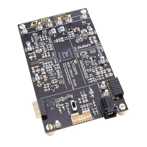
The DC2518A is a demonstration system for the
Power System Manager that interfaces to various regula-
tors. The board contains all the circuitry needed to use
the LTC2975 in a power system and control four power
supplies. The four power supplies include linear and
switching regulators for the purpose of demonstrating a
variety of methods to sense voltage and current. The demo
board provides a sophisticated, digitally programmable
4-channel power supply system.
The LTC2975 is a 4-channel I
System Manager that features accurate input current and
energy measurement. The device monitors input current
and input voltage to calculate input power and energy.
The DC2518A demonstrates the ability of the LTC2975
to sequence, trim, margin, supervise, monitor, and log
faults for four power supplies. The LTC2975 monitors
each channel's output voltage and output current and also
monitors each channel's external temperature sensor and
its own internal die temperature.
The DC2518A board contains four independent power sup-
ply rails. The +12V/–12V rails are based on LDO regulators,
and the +48V/–48V rails are based on DC/DC switching
regulators. The board is pre-configured with these volt-
ages and may be re-configured with feedback resistors.
The LTpowerPlay
graphical user interface (GUI) supports
®
this demonstration system and enables complete control of
all the features of the LTC2975. Together, the LTpowerPlay
software and DC2518A hardware system create a power-
ful development environment for designing and testing
configuration settings of the LTC2975. LTpowerPlay stores
these settings in the LTC2975's internal EEPROM or in a
project file. The software displays all of the configuration
settings and real time measurements from the Power
System Management IC. Telemetry allows easy access
and decoding of the fault log created by the LTC2975.
The board comes pre-programmed with the EEPROM
values appropriate for the four power supply rails on the
DC2518A. Just plug and play!
4-Channel PMBus Power System Manager
with ±12V and ±48V Power Supply Rails
LTC
2975
®
2
C/SMBus/PMBus Power
DEMO MANUAL DC2518A
Order pre-programmed devices from Linear Express
using LTpowerPlay.
The following items are required:
• +12VDC Power Supply
2
• USB-to-I
C/SMBus/PMBus Controller (DC1613)
• LTpowerPlay Software
• PC
DC2518A Features
• Sequence, Trim, Margin, and Supervise Four Power
Supplies
• Manage Faults, Monitor Telemetry, Create Fault Logs
• PMBus Compliant Command Set
• Supported by LTpowerPlay GUI
• Margin or Trim Supplies to 0.25% Accuracy
• Four I
and One I
Monitor
OUT
IN
• Input Power Measurement and Energy Accumulation
• Fast OV/UV Supervisors Per Channel
• Multi-Channel Fault Management
• Automatic Fault Logging to Internal EEPROM
• Operates Autonomously without Additional Software
• Monitors: Voltage, Current, Power, Temperature
• 4-Channel Time-Based Output Sequencer
2
• I
C/SMBus Serial Interface
• Powered from 9V to 14V
Design files for this circuit board are available at
http://www.linear.com/demo/DC2518A
L, LT, LTC, LTM, Linear Technology and the Linear logo, Linear Express and LTpowerPlay are
registered trademarks of Linear Technology Corporation. All other trademarks are the property
of their respective owners.
LTC2975
®
dc2518af
1
Advertisement

Related Manuals for Linear Technology DC2518A


Summary of Contents for Linear Technology DC2518A
- Page 1 LTC2975. L, LT, LTC, LTM, Linear Technology and the Linear logo, Linear Express and LTpowerPlay are The board comes pre-programmed with the EEPROM registered trademarks of Linear Technology Corporation. All other trademarks are the property values appropriate for the four power supply rails on the of their respective owners.
-
Page 2: Performance Summary
DEMO MANUAL DC2518A PERFORMANCE SUMMARY Specifications are at T = 25°C PARAMETER CONDITIONS VALUE VPWR Supply Input Operating Range 9V to 15V VDD33 Supply Input Operating Range 3.13V to 3.47V ADC Total Unadjusted Error ≥ 1V ±0.25% ADC Voltage Sensing Input Range –0.1V to 6V... -
Page 3: Glossary Of Terms
C/SMBus/PMBus Controller (DC1613) observe system response and faults. +12V Power Supply CH0: +12V USB to I C/SMBus/ LTC2975 PSM & CH1: –12V PMBus Controller 4-Ch HV/Neg Demo CH2: +48V (DC1613) Board (DC2518A) CH3: –48V dc2518a F01 Figure 1. DC2518A Demo Setup dc2518af... - Page 4 DC1613 I C/SMBus/PMBus Controller to communicate with environment that supports Linear Technology power system one of many potential targets, including the DC2518A demo management ICs with EEPROM, including the LTC2975 system or a customer board. The software also provides 4-channel Power System Manager. The software supports an automatic update feature to keep the software current a variety of different tasks.
-
Page 5: Quick Start Procedure
DEMO MANUAL DC2518A QUICK START PROCEDURE The following procedure describes how to set up a DC2518A 6. Launch the LTpowerPlay GUI. demo system. a. The GUI automatically identifies the DC2518A and 1. Download and install the LTpowerPlay GUI: builds a system tree for each I C device. - Page 6 DEMO MANUAL DC2518A QUICK START PROCEDURE c. You may make configuration changes. When you If you need to load the original board default configu- update registers in the GUI by using either function ration, select the GUI menu pull-down item DEMO →...
- Page 7 DEMO MANUAL DC2518A DC2518A DETAILS CASCADING CH2 AND CH3 CONNECTOR OUTPUTS LTC2975 PSM DC JACK (+12V) PUSHBUTTON TO FORCE A RESET AND A FAULT DC1613 CONNECTOR C PORTS SWITCH CH0 AND CH1 CASCADING OUTPUTS CONNECTOR Figure 4. DC2518A Details dc2518af...
- Page 8 LTC2975 device is powered either from the DC1613’s 3.3V power or jack power if V is applied. By default all four channels on the DC2518A board are controlled by a single RUN switch. DC2518A LEDs The LTC2975 is pre-configured with different TON_DELAY There are three blue LEDs near the power jack.
- Page 9 Figure 7. TON_DELAY and TOFF_DELAY Settings Margin All Rails The LTC2975 Power System Manageron the DC2518A not only monitors each of the four outputs but can margin the outputs either high or low. Margining is the operation that moves a rail up or down for testing purposes.
- Page 10 Creating a Fault “Why Am I Off?” Tool There is a pushbutton on the DC2518A board that is used to force a fault and demonstrate the demo board’s ability Use the “Why am I Off” tool in the LTpowerPlay GUI to to detect it and respond according to the configuration.
- Page 11 NVM. The most recent monitored values (uptime, voltage, current, temperature) provide additional context preceding the fault. It is a powerful diagnostic feature of the LTC2975 on the DC2518A demo board. Create a Fault Log To create a fault log, check that the fault_log_enable bit is set in the MFR_CONFIG_ALL register.
- Page 12 FAULT pins low. On the NOTE: It is not recommended to short the +48V or –48V DC2518A, the two FAULT pins are tied together, which power supplies directly to GND on this demo board as effectively creates one fault line.
- Page 13 DEMO MANUAL DC2518A ADVANCED DEMO BOARD OPERATIONS Energy Metering The DC2518A demo board has two power supplies that are capable of relatively high voltages, ±48V. Be careful when The LTC2975 is capable of high-side current sensing of handling the board with these channels enabled since the the input power supply.
- Page 14 Output Voltage Sensing Schemes a 100mW rating. The divided voltage is 4.8V, and the pin The voltage sensing schemes employed on the DC2518A current is 9μA. This information can be found in the Typical are of three types. For positive voltage channels (CH0 and Operating Characteristics curve of the LTC2975 data sheet.
- Page 15 ADVANCED DEMO BOARD OPERATIONS Output Current Sensing Schemes REFP +1.232V The output current on each channel of the DC2518A demo SENSEP board uses a 50mΩ sense resistor. This board uses a LTC2975 variety of sensing schemes: IMON, current sense ampli-...
- Page 16 DEMO MANUAL DC2518A ADVANCED DEMO BOARD OPERATIONS Servo Circuits The LTC2975’s DAC is connected directly to the midpoint of the two SET resistors. The R and R resistor SET1 SET2 A number of different servo circuits are utilized on the values are chosen such that the midpoint is approximately DC2518.
- Page 17 DEMO MANUAL DC2518A ADVANCED DEMO BOARD OPERATIONS There are two SET resistors and the midpoint is fed with high and the NFET is released, allowing the LT3081’s a 20μA pre-bias current that sets the floating voltage. The 50μA current source to ramp the SET node via the R SET resistor R always sees 50μA and R...
- Page 18 2. Ensure different slave address settings for each of the into the GUI. boards. The address of each DC2518A board is set by ATTENTION: Once the GUI has launched, click the the DIP switch JP3 on the backside of the board. The “RAM→NVM”...
- Page 19 0x20. The DIP switch settings set the offset. The three switches that may be There is a small DIP switch on the backside of the DC2518A. changed are labeled A0, A1, A2. Examples below set the It is used to set the slave address of an I/O expander which boards to address 0x20 and 0x27.
-
Page 20: Signal Name
DEMO MANUAL DC2518A DC2518A DETAILS TOP Table 3. DC2518A – Default Switch Configuration (Default Position Shown in Grey in the Figure Above) REFERENCE DESIGNATOR SIGNAL NAME USAGE DEFAULT JP3 (Bottom) A0, A1, A2 DIP Switch Used to Set the Address Offset... - Page 21 DEMO MANUAL DC2518A DC2518A DETAILS BOTTOM dc2518af...
- Page 22 DEMO MANUAL DC2518A DC2518A SCHEMATIC DIAGRAM dc2518af...
- Page 23 DEMO MANUAL DC2518A DC2518A SCHEMATIC DIAGRAM dc2518af...
- Page 24 DEMO MANUAL DC2518A DC2518A SCHEMATIC DIAGRAM dc2518af...
- Page 25 Information furnished by Linear Technology Corporation is believed to be accurate and reliable. However, no responsibility is assumed for its use. Linear Technology Corporation makes no representa- tion that the interconnection of its circuits as described herein will not infringe on existing patent rights.
- Page 26 Linear Technology Corporation (LTC) provides the enclosed product(s) under the following AS IS conditions: This demonstration board (DEMO BOARD) kit being sold or provided by Linear Technology is intended for use for ENGINEERING DEVELOPMENT OR EVALUATION PURPOSES ONLY and is not provided by LTC for commercial use. As such, the DEMO BOARD herein may not be complete in terms of required design-, marketing-, and/or manufacturing-related protective considerations, including but not limited to product safety measures typically found in finished commercial goods.
Need help?
Do you have a question about the DC2518A and is the answer not in the manual?
Questions and answers