
Related Manuals for Kuhse KEA 350 P1 Series


Summary of Contents for Kuhse KEA 350 P1 Series
- Page 1 USER MANUAL KEA 350 P1 / KEA 350 RP-P1 Kuhse Power Solutions GmbH An der Kleinbahn 39 21423 Winsen | Germany Fon +49. 4171.798.0 Fax +49. 4171.798.117 www.kuhse.de...
-
Page 2: Table Of Contents
User Manual KEA 350 P1 / KEA 350 RP-P1 Content Amendments ..........................2 Brief Overview ..........................3 Terminal Allocation ........................5 Wiring Diagram ..........................5 Front Panel Access ........................7 3.1.1 Basic Navigation ..........................7 3.1.2 The HOME Screen ........................11 Operation ............................ -
Page 3: Brief Overview
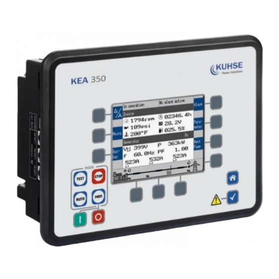
KEA 350 P1 / KEA 350 RP-P1 Brief Overview Fig. 1: KEA 350 RP-P1 Series Fig. 2: KEA 350 P1 Series KEA 350 (-LT) (plastic housing with display) RS-485 interface connector RS-485 #1 KEA 350 RP (sheet metal housing) CAN bus interface connector CAN #1... - Page 4 Opening USB connection to the KEA 3X0 offers read access to the files listed below but with status "delivery" - please be aware that this files are not updated. Please contact Kuhse for the latest versions.
-
Page 5: Terminal Allocation
User Manual KEA 350 P1 / KEA 350 RP-P1 Terminal Allocation Fig. 4: Terminals KEA 3X0-P1(-LT) plastic housing Fig. 5: Terminals KEA 3X0-P1 sheet metal housing Wiring Diagram The Protective Earth terminal 61 is not connected on the sheet metal housing. - Page 6 User Manual KEA 350 P1 / KEA 350 RP-P1 Fig. 6: Wiring diagram KEA 350 RP-P1/KEA 350 P1(-LT) Configurable by LogicsManager Pin 61: Metal housing: don´t use Plastic housing with HMI/display: Earth/ground = 12/24 V SELV BA-KEA 350 P1/ KEA 350 RP-P1_EN Version 03 Seite 6 von 21 Datum: 17.Sep.2020...
-
Page 7: Front Panel Access
User Manual KEA 350 P1 / KEA 350 RP-P1 Front Panel Access The following chapters only apply to model with front panel and display. Front Panel / HMI / display Please see chapter for detailed description of the front panel with display and buttons. Buttons can be disabled by ToolKit with parameter 12978 p. - Page 8 User Manual KEA 350 P1 / KEA 350 RP-P1 Values [1] The "values" section (Fig. 70/1) of the screen illustrates all measured power related information including voltages, currents, frequencies, power, and power factor values. If the mains data display is disabled, the main screen will only show generator data with bigger digits.
- Page 9 User Manual KEA 350 P1 / KEA 350 RP-P1 Group Softkey Caption Description CAN 1 Change to "CAN interface 1 state" screen. CAN 2 Change to "CAN interface 2 state" screen. Ext. I/O Change to external discrete I/Os screen. Int. I/O Change to internal discrete I/Os screen.
- Page 10 User Manual KEA 350 P1 / KEA 350 RP-P1 Status symbols Menu screen Symbol Caption Description Voltage Display Mode The index of the symbol indicates whether delta or wye voltage is Main Screen displayed and which phases are displayed. Generator, mains or busbar rotating field moves clockwise. Single Line Dia- gram Rotating Field CW Generator, mains or busbar rotating field moves counter-clock-...
-
Page 11: The Home Screen
User Manual KEA 350 P1 / KEA 350 RP-P1 The following chapters list notes related to the specific menu screens. For information on standard softkeys and status symbols refer to Chapter 4.1.1 “Basic Navigation” on page 98. 3.1.2 The HOME Screen General notes ... - Page 12 User Manual KEA 350 P1 / KEA 350 RP-P1 Display alternatives The HOME screen allows a number of pre-selectable and soft- button controlled display variants. Generator - Voltages (pp - pn) - selectable via softbutton [1] - Power - Power Factor PF - Frequency - Currents (L1, L2, L3) ...
-
Page 13: Operation
User Manual KEA 350 P1 / KEA 350 RP-P1 Generator/Mains (LS5) - Generator values as described above and additionally for mains values measured by LS-5, if an application mode (parameter 3444 p. 228) with L-MCB is selected. - Voltage - Power - Frequency Fig. -
Page 14: Power On
User Manual KEA 350 P1 / KEA 350 RP-P1 Power ON Behavior during starting KEA 3X0 The start-up procedure of the KEA 3X0 device can be caused by the following reasons: Power ON Power cycling e.g. by 1701 p. 167 “ Set factory default values” ... -
Page 15: Change Operating Modes
User Manual KEA 350 P1 / KEA 350 RP-P1 Power ON from zero power LEDs are twinkling LEDs are illuminated according to the state of the genset control Power cycling Warning LED is twinkling in a high frequency ... - Page 16 User Manual KEA 350 P1 / KEA 350 RP-P1 CAUTION! Hazards due to improper use of operating mode STOP Selecting the operating mode STOP is not the same as an EMERGENCY STOP. In some cases the KEA will perform additional logic functions, such as an engine cool down period, before the engine is stopped.
-
Page 17: Operating Mode Manual
User Manual KEA 350 P1 / KEA 350 RP-P1 4.2.2 Operating Mode MANUAL General usage In the MANUAL operating mode (mode button “MAN” illuminated) both the engine circuit breaker and the power circuit breaker can be operated via the push buttons along the bottom of the display (softkeys). Additionally the Start(I)/Stop(O) buttons can be used to start or stop the engine. - Page 18 User Manual KEA 350 P1 / KEA 350 RP-P1 Overview Function/Status Symbol Available in application mode Start/running engine Stop/stand still engine ...
-
Page 19: Operating Mode Automatic
User Manual KEA 350 P1 / KEA 350 RP-P1 Symbol Description Generator or mains rotating field moves clockwise. Generator or mains rotating field moves counter-clockwise. Power is detected at the respective measuring point (gene-rator, busbar, or mains). Indicates that the engine delayed monitoring has expired and the monitoring functions are enabled. -
Page 20: Operating Mode Test
User Manual KEA 350 P1 / KEA 350 RP-P1 Auto mains failure operation (AMF) Auto mains failure operation is only available in application mode If the AUTOMATIC operating mode is enabled and the mains fail, the engine and the power circuit breakers will be operated according to the current application mode. -
Page 21: Restore Language Setting Via Hmi, Buttons And Softkeys
User Manual KEA 350 P1 / KEA 350 RP-P1 Restore Language Setting via HMI, Buttons and Softkeys In order to change the language setting via HMI, press the (soft)keys in the following order: Language parameter is on code level "0", so the instruction will work with each code level.
Need help?
Do you have a question about the KEA 350 P1 Series and is the answer not in the manual?
Questions and answers