Table of Contents
Advertisement
Quick Links
S
TA112MX3-E
07-01-25
Replaces: January 2006
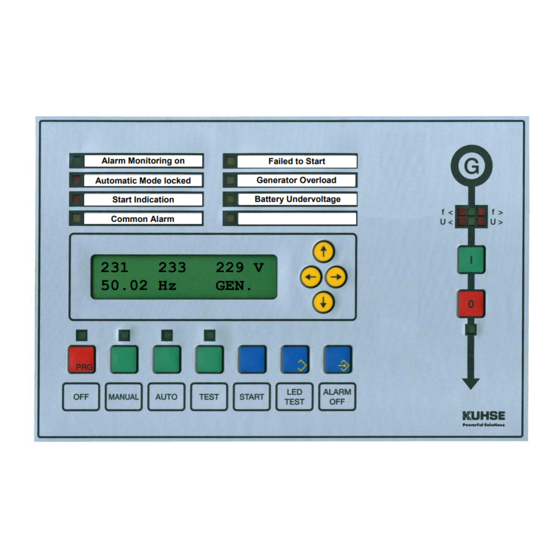
Alarm Monitoring on
Automatic Mode locked
Start Indication
Common Alarm
231
50.02 Hz
The control unit KEA 112 MOBL is used for stand-alone (mobile) gensets. The complete engine and
generator protection is included. The relay functions and the parameters can be set by software. The
automatic control unit uses the RZ 071-D of the KEA 070 series. As the KEA 112 has the same size and is
mounted in the same manner as the former KEA 072, it can be interchanged without difficulty.
Exchangeable paper strips label for four user defined LED-indicators and four operation indicators. All
alarms, all actual and reference values are shown on the display. The illuminated display shows two lines of
16 characters with a character height of 10 mm, so that it can easily be read from a large distance. The
parameters can be set by the keys and the display or with the ParaWin software via the serial interface
(optical fibre).
The hardware for this KEA is fixed and cannot be extended.
The control unit is easy to operate as it is operated without menu navigation
but directly by the usual keys as all the previous control units.
Alfred Kuhse GmbH, D-21423 Winsen/Luhe, An der Kleinbahn 39. Telefon +49 (0)4171 798-0, Fax +49 (0)4171 798-117, http://www.kuhse.de
Operation Manual
Start-Stop Control Unit
for Stand-alone Gensets
KEA 112 MOBL
Generator Overload
Battery Undervoltage
233
229 V
GEN.
Important information!
Failed to Start
Advertisement
Table of Contents

Related Manuals for Kuhse KEA 112 MOBL


Summary of Contents for Kuhse KEA 112 MOBL
- Page 1 The control unit is easy to operate as it is operated without menu navigation but directly by the usual keys as all the previous control units. Alfred Kuhse GmbH, D-21423 Winsen/Luhe, An der Kleinbahn 39. Telefon +49 (0)4171 798-0, Fax +49 (0)4171 798-117, http://www.kuhse.de...
-
Page 2: Table Of Contents
TA112MX3-E - 2 / 18 - 07-01-25 CONTENTS − C Functions Page 3 Page 5 OMMON LARM Basic operation Page 3 − Four customer designed indicators Page 6 Handling of the display Page 3 − Mimic diagram / Voltage monitor Page 6 −... -
Page 3: Ta112Mx3-E
PERATION OF THE ONTROL The control unit is simple to operate by the push buttons and without menu navigation as all previous KUHSE models. The operation mode is selected via four keys. In M and T modes, the generator ANUAL supply is executed using the buttons that are arranged in the mimic diagram. - Page 4 General Parameters, Group 0 Control unit type is displayed. KEA 112 MOBL KUHSE GmbH Display of the KUHSE order number and the control units production 90567 ORDER NMR number. This information is important for later contact with the factory. 12345 F-NUMBER Software date and version number.
-
Page 5: Common Alarm
TA112MX3-E - 5 / 18 - 07-01-25 ISPLAY AND UTTONS Important operation indicators Customer defined indicators Alarm Monitoring on Failed to Start Automatic Mode locked Generator Overload Generator voltage Start Indication Battery Undervoltage Common Alarm Gen.CB On button Disp lay, illuminated lines, each with 16 characte rs, 10 mm high... -
Page 6: Four Customer Designed Indicators
TA112MX3-E - 6 / 18 - 07-01-25 OUR CUSTOMER DESIGNED INDICATORS The function of the four indicators of the right row can be set as required. You can use them to announce selected important alarms (in addition to the display) or for system messages. You can also use digital inputs (e.g. -
Page 7: Warning Notes
TA112MX3-E - 7 / 18 - 07-01-25 ARNING OTES − Care must be taken when connecting the device, as it may be destroyed if incorrectly connected. − All details of the connection specifications must be fulfilled. − The PE(N) must be connected for security reasons to terminal 5 on the X403. −... -
Page 8: Technical Data
TA112MX3-E - 8 / 18 - 07-01-25 ECHNICAL KEA Controller − Device for frontal installation, dimensions: (⇒,⇑, depth) 260 x 170 x 100 mm, − Weight approx. 2.2 kg, can be installed wherever required, − Protection class (installed) IP 44, −... -
Page 9: Operation Modes
112-MOBL-3 PERATION ODES PERATION ODES The operation modes can be selected using four buttons. The LED above the corresponding button indicates the selected operation mode. The buttons can be electrically locked via an input (e.g. by connecting an external key-operated switch), to prevent unauthorised or accidental change of an operation mode. The operation modes described further down can be activated with these buttons. -
Page 10: Operation Mode Test
112-MOBL-3 PERATION ODES In the case of a Remote start command with generator operation, the genset is started and switches the generator CB on. The Start without generator operation can be used, for example, to supply more delicate consumers. If, for example, the generator power is sudden needed, the genset can be started up via this input. -
Page 11: Alarm Monitoring
112-MOBL-3 LARM ONITORING LARM ONITORING The control unit can control up to 48 alarms. The texts and trigger inputs for alarms 1 to 19 are variable, i.e. their texts and actuation are determined by the parameterisation program P . The alarms are actuated by contact inputs (ports 1 to 14 or free inputs of the relay unit RZ 071-D) or by internal flags (e.g. -
Page 12: Engine Does Not Come To A Standstill
112-MOBL-3 LARM ONITORING XPLANATION OF LARMS Engine does not come to a standstill This alarm is announced when the engine is still running after the stop procedure. This signalises that the stopping equipment of the engine (stopping solenoid, gas valve, etc.) is defective. Engine fails to start This alarm comes up (and the automatic operation is locked) when the engine is not running when the start sequence is over. -
Page 13: Running Hours Till Maintenance Elapsed
112-MOBL-3 LARM ONITORING Running hours till maintenance elapsed The remaining running hours till the maintenance of the engine is show in A . A warning CTUAL ALUES alarm (if programmed) is given if the time period has elapsed. The counter for the time period till the next maintenance must be set after the first one is done. -
Page 14: Response Diagram For Thermal Overload
112-MOBL-3 LARM ONITORING ESPONSE IAGRAM FOR HERMAL VERLOAD Class 10A Response delay 1h20' 40'' 20'' 10'' 1 1.2 1.5 x preset current (I OCUMENT ISTORY OF LARM ONITORING Revision Modification Released Revision Modification Released 06-01-11 First edition 05-12-02 07-01-25 Maintenance alarms 07-01-25 Alarm Monitoring 112-MOBL-3 / 07-01-25 14 / 18... -
Page 15: Actual Values
112-MOBL-3 CTUAL ALUES CROLLING OF ACTUAL ALUES The A group is selected with the [←] and [→] buttons or by pressing LED T and [←] at CTUAL VALUES the same time. The below listed actual value can then be selected with the keys [↓] (down) and [↑] (up). The selection starts again with the other end of the 'page', when the top or bottom is reached. - Page 16 112-MOBL-3 CTUAL ALUES OTES Running hours till next maintenance The running hours till next maintenance are counted down from a preset value. An alarm (if programmed) is triggered if the counter reaches 000000. A can be provided. The maintenance must GOODWILL PERIOD be done during this period.
-
Page 17: Additional Functions
112-MOBL-3 DDITIONAL UNCTIONS DDITIONAL UNCTIONS REQUENCY ONTROL FOR ISOLATED PERATION A lower and an upper limit are preset for the frequency controlling. No commands are given to the engine if the actual frequency is in the dead band between the upper and the lower frequency. Corresponding commands are given if the frequency is outside of this window. - Page 18 112-MOBL-3 DDITIONAL UNCTIONS OCUMENT ISTORY DDITIONAL UNCTIONS Revision Modification Released Revision Modification Released Date Date 06-01-11 First edition 06-01-11 07-01-25 Format 07-01-25 Additional Functions 112-MOBL-3 / 07-01-25 18 / 18 Changes without further notice reserved.
Need help?
Do you have a question about the KEA 112 MOBL and is the answer not in the manual?
Questions and answers