Table of Contents
Advertisement
Quick Links
SA101NX3-E
07-01-25
Replaces: 06-08-08
−
Care must be taken when connecting the device, as it may be destroyed if incorrectly connected.
−
All details of the connection specifications must be fulfilled.
−
The PE(N) must be connected for security reasons to terminal 5 on the X403.
−
The leakage current of the noise filters is 22 mA in case of a 2-phase voltage lost.
−
Only adequately qualified personnel should undertake the installation and commissioning.
−
The relevant regulations, especially the VDE regulations, must be observed.
−
The S
M
ERVICE
ANUAL
−
The device must be parameterised in such a way that any risk to persons or property is prevented.
−
The charging device must be switched off before the battery is disconnected.
−
The negative pole of the battery must be grounded at the input terminal of the switchboard. The
minimum conductor cross-section is 10 mm
−
The screens of the analogue input wiring must be connected to the earth screws on the KEA cover, and
must have no connection to any other metal parts.
−
The supply voltage can be set to 12 or 24 V DC with a switch on the RZ 071-D.
−
When the supply voltage of the control unit has been switched off, you must wait at least 20 seconds
before applying it again.
−
All coils must be fitted with reverse diodes to prevent high voltage peaks. All other coils or inductive
loads must also be fitted with suppressor elements. The same applies for all relays and inductors that are
used in the switchboard or controlled externally.
−
The shielding of the analogue wiring must only be connected the earth screws beside the terminal strip
X 401 and may have no galvanic connection to any other metal parts.
PIN number, I
-N
DENT
Revision
Modification
11/2005
First edition
01/2006
06-06-06
Format
06-08-08
Menu structure
07-01-25
Menu structure
Alfred Kuhse GmbH, D-21423 Winsen/Luhe, An der Kleinbahn 39. Phone +49 (0)4171 798-0, Fax +49 (0)4171 798-117, http://www.kuhse.de
Service Manual
Start-Stop Control Unit
for Emergency Power plants
KEA 101 NSTR
W
should be read carefully before commissioning.
Page 2
Page 2
Page 3
Page 3
Page 3
UMBER
D
OCUMENT
Released
05-11-30
06-01-11
06-06-06
06-08-08
07-01-25
N
ARNING
OTES
2
.
C
ONTENTS
Connection of RZ 071-D
H
ISTORY
Revision
Page 4
Page 5
Page 7
Page 8
Modification
Changes without further notice reserved.
Released
Advertisement
Table of Contents

Related Manuals for Kuhse KEA 101 NSTR


Summary of Contents for Kuhse KEA 101 NSTR
- Page 1 01/2006 Connection of RZ 071-D 06-01-11 06-06-06 Format 06-06-06 06-08-08 Menu structure 06-08-08 07-01-25 Menu structure 07-01-25 Changes without further notice reserved. Alfred Kuhse GmbH, D-21423 Winsen/Luhe, An der Kleinbahn 39. Phone +49 (0)4171 798-0, Fax +49 (0)4171 798-117, http://www.kuhse.de...
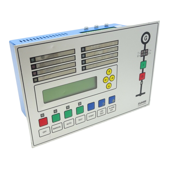
- Page 2 SA101NX3-E - 2 / 8 - 07-01-25 ESIGN The control unit is incorporate into the front door of the switchboard. The front meets the protection class IP 44 when installed. The two rows of LEDs are marked with interchangeable labels. The relay unit is mounted on the mounting plate and linked to the control unit in the door with the supplied cable.
- Page 3 SA101NX3-E - 3 / 8 - 07-01-25 PERATION OF THE ISPLAY Values or parameters are selected, as you would read a book. The further down listed groups are arranged as 'pages'. You can scroll forwards and backwards through these groups by pressing the [→] and [←] keys. The entries of each group can be read from top to bottom like lines of a text.
- Page 4 SA101NX3-E - 4 / 8 - 07-01-25 ARAMETERISATION Menu structure *) Group 0 Group Group 2 Group 3 Group 4 KEA 101 NSTR ACTUAL VALUES ENCODING OF MAINS VOLTAGE GENERATOR KUHSE GmbH ALARMS MONITOR VOLTAGE MONITOR COUNTERS GEN.CURRENT MONITOR Group 5...
- Page 5 SA101NX3-E - 5 / 8 - 07-01-25 RZ 071-D ONNECTION OF ELAY UNIT The contacts for the terminals 1 to 28 must be connected to [L-] potential. Terminal 29 is provided to be connected to terminal D+ of the charging dynamo. The "running" signal is active when the voltage exceeds about 8 volts DC.
- Page 6 SA101NX3-E - 6 / 8 - 07-01-25 This function does not meet the requirements of the German Standards DIN VDE 0107, because a running genset will not be shut down; this function only protects the engine before start-up. Terminal 25: Remote start without load transfer. The genset starts in the automatic mode without the generator being switched on when a command is issued to this terminal.
- Page 7 SA101NX3-E - 7 / 8 - 07-01-25 ECHNICAL KEA Controller − Device for frontal installation, dimensions: (⇒,⇑, depth) 260 x 170 x 100 mm, − Weight approx. 2.2 kg, can be installed wherever required, − Protection class (installed) IP 44, −...
- Page 8 SA101NX3-E - 8 / 8 - 07-01-25 RDER NUMBER CODES Order number 2A101 Example: Control unit for emergency power plants, Mains Generator mains and generator voltage 230/400 V, 3 x 100 Volt 3 x 100 Volt current transformer of generator ../5 A: 3 x 100 Volt 230/400 Volt The order number is 2A101N53...
Need help?
Do you have a question about the KEA 101 NSTR and is the answer not in the manual?
Questions and answers