Table of Contents
Advertisement
Quick Links
Service Manual
for product: KEA 201 ERSY:
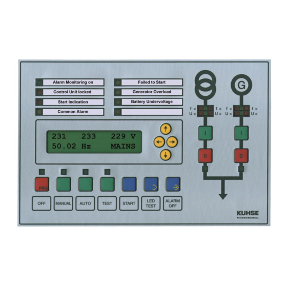
Control Unit for Emergency Power Gensets
with Overlapping Synchronisation
File: SA_KEA 201 ERSY_EN_Ver 2016-07-01
1.
Design
The control unit is incorporate into the front door of the switchboard. The front meets the protection class
IP 44 when installed. The two rows of LEDs are marked with interchangeable labels. The relay units are
mounted on the mounting plate and linked to the control unit in the door with the supplied cable.
The control unit has an optic fibre or a USB interface - switches automatically - for the connection of a PC.
By means of the parameterisation program P
analogue readouts are possible. Parameterisation can also be performed at the display.
1.1.
Parameterisation
1. Additional Interface CAN
2. Additional Parameters
3. Alarm Remote cancelling
4. Alarms
5. Analogue Inputs
6. Analogue Outputs
7. Battery Monitor
8. CAN 0
9. Frequency Controller at isolated Operation
10. Generator Current Monitor
11. Generator Voltage Monitor
12. Hardware
Alfred Kuhse GmbH
An der Kleinbahn 39, D-21423 Winsen (Luhe)
W
, the following settings (password-protected) and
ARA
IN
Phone: +49 4171-798-0
kuhse@kuhse.de
Fax +49 4171-798-117
www.kuhse.de
13. Internal Synchronizer
14. J1939 engine management
15. J1939 hide analogue values
16. Mains Voltage Monitor
17. Modem
18. ProMerk. Programmable Flags
19. Relay and Indicator Functions
20. Speed Monitoring and Control
21. Sprinkler Operation
22. Starting and Stopping
23. Transfer Mains – Generator
24. Voltage Controller
Changes without further notice
reserved.
Advertisement
Table of Contents

Related Manuals for Kuhse KEA 201 ERSY


Summary of Contents for Kuhse KEA 201 ERSY
-
Page 1: Design
Service Manual for product: KEA 201 ERSY: Control Unit for Emergency Power Gensets with Overlapping Synchronisation File: SA_KEA 201 ERSY_EN_Ver 2016-07-01 Design The control unit is incorporate into the front door of the switchboard. The front meets the protection class IP 44 when installed. -
Page 2: Table Of Contents
Service Manual for KEA 201 ERSY – File: SA_KEA 201 ERSY_EN_Ver 2016-07-01.doc 2 / 12 2 / 12 1.2. Analogue Readouts Actual values: - Voltages - Currents - Active and apparent load - Power factor - Speed - Battery voltage,... -
Page 3: Safety Instructions
Service Manual for KEA 201 ERSY – File: SA_KEA 201 ERSY_EN_Ver 2016-07-01.doc 3 / 12 3 / 12 11.1. KEA Controller .......................... 8 11.2. Analogue Inputs and Outputs ....................8 11.3. Relay Unit RZ 071-D ......................... 8 11.4. Relay unit RZ 071-E (optional) ....................8 11.5. -
Page 4: Connections
Service Manual for KEA 201 ERSY – File: SA_KEA 201 ERSY_EN_Ver 2016-07-01.doc 4 / 12 4 / 12 Connections 1. Trained experts may only make the connections of the KEA. 2. The PE(N) must be connected for security reasons to terminal 5 on the X403. -
Page 5: Operating The Display
Service Manual for KEA 201 ERSY – File: SA_KEA 201 ERSY_EN_Ver 2016-07-01.doc 5 / 12 5 / 12 Operating the Display Values or parameters are selected, as you would read a book. The further down listed groups are arranged as 'pages'. You can scroll forwards and backwards through these groups by pressing the [→] and [←] keys. -
Page 6: Parameterisation Menu Structure
Service Manual for KEA 201 ERSY – File: SA_KEA 201 ERSY_EN_Ver 2016-07-01.doc 6 / 12 6 / 12 Parameterisation Menu structure Group 0 Group Group 2 Group 3 Group 4 KEA 201 ERSY ACTUAL VALUES ENCODING OF MAINS VOLTAGE GENERATOR... -
Page 7: Terminal 19: Immediate Stop
Service Manual for KEA 201 ERSY – File: SA_KEA 201 ERSY_EN_Ver 2016-07-01.doc 7 / 12 7 / 12 Terminal 19: I MMEDIATE The signal can be parameterised as normally-closed or normally-open. The genset will be immediately shut down if a signal is applied to this terminal. -
Page 8: Technical Data
CAN bus interface to engine management (the protocol must be known and implemented) 11.6. Connection to other Systems (optional) Device for attachment on a mounting rail: KNG (Kuhse Network Gateway) to connect to other systems via Profibus DP or Modbus RTU Alfred Kuhse GmbH Phone: +49 4171-798-0 kuhse@kuhse.de... - Page 9 Service Manual for KEA 201 ERSY – File: SA_KEA 201 ERSY_EN_Ver 2016-07-01.doc 9 / 12 9 / 12 Diagrams 12.1. Connection Diagram, RZ-071-D Alfred Kuhse GmbH Phone: +49 4171-798-0 kuhse@kuhse.de Changes without further notice An der Kleinbahn 39, D-21423 Winsen (Luhe) Fax +49 4171-798-117 www.kuhse.de...
- Page 10 Service Manual for KEA 201 ERSY – File: SA_KEA 201 ERSY_EN_Ver 2016-07-01.doc 10 / 12 10 / 12 12.2. Connections Diagram, RZ-071-E (optional) 12.3. Connection Diagram, KEA 201 ERSY Alfred Kuhse GmbH Phone: +49 4171-798-0 kuhse@kuhse.de Changes without further notice...
- Page 11 Service Manual for KEA 201 ERSY – File: SA_KEA 201 ERSY_EN_Ver 2016-07-01.doc 11 / 12 11 / 12 12.4. Connections, analogue Inputs Alfred Kuhse GmbH Phone: +49 4171-798-0 kuhse@kuhse.de Changes without further notice An der Kleinbahn 39, D-21423 Winsen (Luhe) Fax +49 4171-798-117 www.kuhse.de...
- Page 12 12 / 12 Service Manual for KEA 201 ERSY – File: SA_KEA 201 ERSY_EN_Ver 2016-07-01.doc 12 / 12 Drilling Template, Scale 1:1 – print without scaling! Alfred Kuhse GmbH Phone: +49 4171-798-0 kuhse@kuhse.de Changes without further notice An der Kleinbahn 39, D-21423 Winsen (Luhe) Fax +49 4171-798-117 www.kuhse.de...
Need help?
Do you have a question about the KEA 201 ERSY and is the answer not in the manual?
Questions and answers