
Related Manuals for Trillium 8-WSP


Summary of Contents for Trillium 8-WSP
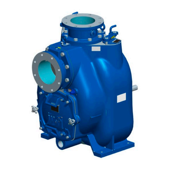
- Page 1 Self-Priming Pumps Installation, Operation & Maintenance Instructions Model 8-WSP WSP-D300_8 Trillium Flow Technologies Tel: 801-359-8731 Fax: 801-530-7531 © Copyright 2019, The Factory. All rights reserved.
-
Page 2: Table Of Contents
WSP™ DATA SHEET WSP™ SELF-PRIMER PUMPS WSP-D300_8 Rev. 3 01/09/20 INTRODUCTION ....................4 PURPOSE ......................4 SAFETY ......................5 III. PREVENTIVE MAINTENANCE ..............13 DISASSEMBLY & REASSEMBLY OF THE PUMP & SEAL ......15 REMOVING THE COVER PLATE & WEARPLATE ........17 REMOVING THE SUCTION CHECK VALVE .......... - Page 3 WSP™ DATA SHEET WSP™ SELF-PRIMER PUMPS WSP-D300_8 Rev. 3 01/09/20 Valves ......................45 Bypass Lines ..................... 45 G. WSP™ AUTOMATIC AIR RELEASE VALVE (WSP™ ARV) ......47 Theory of Operation ................... 47 WSP™ Air Release Valve Installation ............49 H. ALIGNMENT ....................50 Coupled Drives ..................
-
Page 4: Introduction
WSP™ DATA SHEET WSP™ SELF-PRIMER PUMPS WSP-D300_8 Rev. 3 01/09/20 INSTALLATION, OPERATION AND MAINTENANCE INSTRUCTIONS INTRODUCTION Warning levels applying to the safe installation, operation and maintenance of all sizes of WSP™ Self-Primer (WSP) pumps can be located at the beginning of this manual. -
Page 5: Safety
WSP™ DATA SHEET WSP™ SELF-PRIMER PUMPS WSP-D300_8 Rev. 3 01/09/20 IMMEDIATE HAZARDS WHICH WILL RESULT IN SEVERE PERSONAL INJURY OR DEATH. THESE INSTRUCTIONS DESCRIBE PROCEDURE REQUIRED AND THE INJURY WHICH WILL RESULT FROM FAILURE TO FOLLOW THE PROCEDURE. HAZARDS OR UNSAFE PRACTICES WHICH COULD RESULT IN SEVERE PERSONAL INJURY OR DEATH. - Page 6 WSP™ DATA SHEET WSP™ SELF-PRIMER PUMPS WSP-D300_8 Rev. 3 01/09/20 WHEN A MANUAL SHUT-OFF VALVE IS INSTALLED IN A BYPASS LINE, IT MUST REMAIN OPEN DURING OPERATION. CLOSING THE MANUAL SHUT-OFF VALVE COULD CAUSE A PUMP, WHICH HAS LOST PRIME, TO CONTINUE TO OPERATE WITHOUT REACHING PRIME.
- Page 7 WSP™ DATA SHEET WSP™ SELF-PRIMER PUMPS WSP-D300_8 Rev. 3 01/09/20 ONCE THE PUMP HAS BEEN POSITIONED, ENSURE THAT ALL PUMP AND PIPING CONNECTIONS ARE TIGHTENED, SECURED, AND SUPPORTED PROPERLY. ALL GUARDS AND PROTECTIVE DEVICES MUST BE INSTALLED BEFORE THE PUMP IS STARTED.
- Page 8 WSP™ DATA SHEET WSP™ SELF-PRIMER PUMPS WSP-D300_8 Rev. 3 01/09/20 ENSURE THAT THE BYPASS LINE IS DIRECTED BACK INTO THE WET-WELL OR TANK TO PREVENT HAZARDOUS SPILLS AS SOME LEAKING (1 TO 5 GALLONS [3.8 TO 19 LITERS] PER MINUTE) WILL OCCUR WHEN THE VALVE IS IN THE FULL-CLOSED POSITION.
- Page 9 WSP™ DATA SHEET WSP™ SELF-PRIMER PUMPS WSP-D300_8 Rev. 3 01/09/20 NO PERSON SHOULD ATTEMPT TO OPEN OR SERVICE THIS PUMP BEFORE BECOMING THOROUGHLY FAMILIAR WITH ALL THE PROCEDURES OUTLINED IN THIS MANUAL. PLEASE STUDY THESE INSTRUCTIONS CAREFULLY. WHEN PERFORMING EQUIPMENT MAINTENANCE, THE EQUIPMENT ELECTRICAL SERVICE MUST BE LOCKED OUT WITH AN APPROVED LOCKOUT AND KEY.
- Page 10 WSP™ DATA SHEET WSP™ SELF-PRIMER PUMPS WSP-D300_8 Rev. 3 01/09/20 PRESSURE WITHIN THE PUMP MAY CAUSE PARTS TO BECOME DISENGAGED AND EXPELED VIOLENTLY, CAUSING POTENTIAL SEVERE INJURY TO PERSONNEL. ALWAYS ALLOW THE PUMP TO COOL BEFORE SERVICING. THIS PUMP SHOULD ONLY BE OPERATED IN THE DIRECTION SHOWN ON THE ARROW ON THE PUMP BODY AND ON ANY ACCOMPANYING DECALS.
- Page 11 WSP™ DATA SHEET WSP™ SELF-PRIMER PUMPS WSP-D300_8 Rev. 3 01/09/20 PUMP PERFORMANCE INCLUDING SPEED AND OPERATING CONDITIONS ARE REQUIRED TO BE WITHIN THE RANGE SHOWN ON THE MANUFACTURER’S PUMP PERFORMANCE CURVE. THIS PUMP SHOULD ALWAYS BE OPERATED WITH LIQUID IN THE PUMP CASING. WHEN OPERATING THE PUMP DRY, THE PUMP WILL NOT PRIME.
- Page 12 WSP™ DATA SHEET WSP™ SELF-PRIMER PUMPS WSP-D300_8 Rev. 3 01/09/20 PUSH AGAINST THE OUTER RACE DURING INSTALLATION OF THE BEARINGS INTO THE BEARING BORE. NEVER STRIKE THE BALL CAGE OR BALLS. ANY TIME THE OLD SEAL IS REMOVED FROM THE PUMP A NEW SEAL ASSEMBLY SHOULD BE INSTALLED.
-
Page 13: Preventive Maintenance
WSP™ DATA SHEET WSP™ SELF-PRIMER PUMPS WSP-D300_8 Rev. 3 01/09/20 INSTALLATION AND OPERATION OF THE PUMPS AND ASSOCIATED EQUIPMENT MUST BE IN ACCORDANCE WITH ALL NATIONAL AND LOCAL CODES, AS WELL AS INDUSTRY STANDARDS. REGULARLY OBSERVE THE CONDITION OF THE BEARING LUBRICANT FOR SIGNS OF RUST OR MOISTURE, ESPECIALLY IN AREAS WHERE VARYING HOT AND COLD TEMPERATURES ARE TYPICAL. - Page 14 WSP™ DATA SHEET WSP™ SELF-PRIMER PUMPS WSP-D300_8 Rev. 3 01/09/20 Preventive Maintenance Guide Service Daily Owner Status Notes Check the following: Check the overall condition of the pump Notice: Hardware for tightness Are there any leaks? Is there unusual vibration? Monitor and record the gauge readings Are the speed and flow normal? Service...
-
Page 15: Disassembly & Reassembly Of The Pump & Seal
The first set of characters in the pump name describes the size and model of the pump (8-WSP is an 8” self-primer). Use the following key to determine the materials used in the pump from the remaining characters in the pump name. - Page 16 * This letter indicates a Ductile Iron pump case with a Hi-Chrome Cover Plate. A Hi- Chrome case is not available. For example, 8-WSP-BBBBB-B1-BLG is a stainless pump with a stainless ANSI flange, stainless hardware, nitrile o-rings, and Type 2 tungsten carbide seal.
-
Page 17: Removing The Cover Plate & Wearplate
WSP™ DATA SHEET WSP™ SELF-PRIMER PUMPS WSP-D300_8 Rev. 3 01/09/20 NO PERSON SHOULD ATTEMPT TO OPEN OR SERVICE THIS PUMP BEFORE BECOMING THOROUGHLY FAMILIAR WITH ALL THE PROCEDURES OUTLINED IN THIS MANUAL. PLEASE STUDY THESE INSTRUCTIONS CAREFULLY. WHEN PERFORMING EQUIPMENT MAINTENANCE, THE EQUIPMENT ELECTRICAL SERVICE MUST BE LOCKED OUT WITH AN APPROVED LOCKOUT AND KEY. -
Page 18: Removing The Suction Check Valve
WSP™ DATA SHEET WSP™ SELF-PRIMER PUMPS WSP-D300_8 Rev. 3 01/09/20 Figure 1 Disengage the hardware to remove the wearplate then inspect it and replace if it is badly gouged or worn. Carefully inspect the O-rings in the back cover and replace if worn or damaged. B. - Page 19 WSP™ DATA SHEET WSP™ SELF-PRIMER PUMPS WSP-D300_8 Rev. 3 01/09/20 While the impeller rotation still has a block (Figure 3), use a piece of long, heavy bar to lever against the arm of the lathe dog in a counterclockwise direction (You should be facing the drive end of the shaft.).
- Page 20 WSP™ DATA SHEET WSP™ SELF-PRIMER PUMPS WSP-D300_8 Rev. 3 01/09/20 Figure 3 Remove hardware attaching the rotating assembly to the pump casing. Use the jackbolts to detach the rotating assembly by pulling directly away from the pump casing, then tag and tie the rotating assembly shims to simplify reassembly. NOTE: If you prefer, a tool for disassembly may be obtained from Weir Specialty Pumps.
-
Page 21: Removing The Impeller
WSP™ DATA SHEET WSP™ SELF-PRIMER PUMPS WSP-D300_8 Rev. 3 01/09/20 When installing the tool, remove the vented plug from the bearing housing, then screw the longest pipe length into the vent hole until completely attached. Fasten the tee, and screw in both handles. Be very careful when lifting the rotating assembly. -
Page 22: Removing & Disassembling The Shaft & Bearing
WSP™ DATA SHEET WSP™ SELF-PRIMER PUMPS WSP-D300_8 Rev. 3 01/09/20 With the sealplate on a level surface, impeller side down, use a wooden dowel or other appropriate tool to press the backside of the stationary seat until both the seat and the O-rings are loose enough to remove then take out the shaft sleeve O-ring. -
Page 23: Disassembly Of The Two-Piece Bearing Housing
WSP™ DATA SHEET WSP™ SELF-PRIMER PUMPS WSP-D300_8 Rev. 3 01/09/20 BEFORE USING ANY CLEANING SOLVENTS CAREFULLY READ AND FOLLOW ALL PRECAUTIONS PRINTED ON THE SOLVENT CONTAINER. CLEANING SOLVENTS ARE KNOWN TO BE TOXIC AND FLAMMABLE AND ARE ONLY TO BE USED IN WELL- VENTILATED AREAS AWAY FROM EXCESSIVE HEAT, SPARKS, AND FLAMES. -
Page 24: Reassembling The Two-Piece Bearing Housing
WSP™ DATA SHEET WSP™ SELF-PRIMER PUMPS WSP-D300_8 Rev. 3 01/09/20 Figure 6 H. REASSEMBLING THE TWO-PIECE BEARING HOUSING Replace and lubricate the O-ring. Place the inner bearing housing half into the outer bearing housing half and install all the bolts and lock washers (See Figure 6). Torque the bolts to 67 lb-ft for dry threads and 40 lb-ft for lubricated threads. - Page 25 WSP™ DATA SHEET WSP™ SELF-PRIMER PUMPS WSP-D300_8 Rev. 3 01/09/20 Carefully inspect the pump shaft for nicks or scratches, any distortion, or for thread damage on the impeller end. Use a fine file or emery cloth to remove small nicks and burrs.
- Page 26 WSP™ DATA SHEET WSP™ SELF-PRIMER PUMPS WSP-D300_8 Rev. 3 01/09/20 NEVER PRESS OR HIT AGAINST THE OUTER RACE, BALLS, OR BALL CAGE DURING BEARING INSTALLATION ONTO THE SHAFT. PRESS THE INNER RACE ONLY. Use the bearing snap ring to attach the outboard bearing on the shaft. Weir Specialty Pumps recommends the use of a WSP shaft installation tool or a properly tapered sleeve if the WSP shaft tool in unavailable.
-
Page 27: Installing The Mechanical Seal
WSP™ DATA SHEET WSP™ SELF-PRIMER PUMPS WSP-D300_8 Rev. 3 01/09/20 J. INSTALLING THE MECHANICAL SEAL BEFORE USING ANY CLEANING SOLVENTS CAREFULLY READ AND FOLLOW ALL PRECAUTIONS PRINTED ON THE SOLVENT CONTAINER. CLEANING SOLVENTS ARE KNOWN TO BE TOXIC AND FLAMMABLE AND ARE ONLY TO BE USED IN WELL- VENTILATED AREAS AWAY FROM EXCESSIVE HEAT, SPARKS, AND FLAMES. - Page 28 WSP™ DATA SHEET WSP™ SELF-PRIMER PUMPS WSP-D300_8 Rev. 3 01/09/20 FINISHED FACES CANNOT BE REALIGNED. PREMATURE SEAL FAILURE WILL RESULT FROM USING AN OLD SEAL. Facilitate seal installation by lubricating the shaft sleeve O-ring and the external stationary seat O-ring with a tiny amount of light lubricating oil. (Figure 9 shows seal part identification).
-
Page 29: Mechanical Seal Installation
WSP™ DATA SHEET WSP™ SELF-PRIMER PUMPS WSP-D300_8 Rev. 3 01/09/20 WHEN REUSING AN OLD SEAL, DO NOT ATTEMPT TO SEPARATE THE ROTATING PORTION OF THE SEAL FROM THE SHAFT SLEEVE. DURING USE THE RUBBER BELLOWS WILL BOND TO THE SLEEVE AND ATTEMPTING TO SEPARATE THEM WILL DAMAGE THE BELLOWS. -
Page 30: Cartridge Seal Installation
WSP™ DATA SHEET WSP™ SELF-PRIMER PUMPS WSP-D300_8 Rev. 3 01/09/20 Once the seal is replaced, install and adjust the impeller/seal plate clearance (.025” to .040”). 2. Cartridge Seal Installation 1. Install the seal plate gasket if the seal plate was previously removed. Carefully place the seal plate directly over the shaft, and attach it to the bearing housing with its hardware. - Page 31 WSP™ DATA SHEET WSP™ SELF-PRIMER PUMPS WSP-D300_8 Rev. 3 01/09/20 To obtain a clearance of .025 to .040 of an inch for optimal pump efficiency, measure the clearance between the impeller and the sealplate. Remove the impeller and remove an adequate amount of adjusting shims to ensure adequate clearance is obtained.
-
Page 32: Installing The Rotating Assembly
WSP™ DATA SHEET WSP™ SELF-PRIMER PUMPS WSP-D300_8 Rev. 3 01/09/20 L. INSTALLING THE ROTATING ASSEMBLY Lubricate the bearing housing O-ring with light grease then install by easing the rotating assembly into the pump casing. Use the installation tool for this procedure being careful to avoid damaging the O-ring. - Page 33 WSP™ DATA SHEET WSP™ SELF-PRIMER PUMPS WSP-D300_8 Rev. 3 01/09/20 Figure 10 Figure 11 Generously lubricate the back cover O-rings with No. 2 grease. Remove and clean all debris or scale from the pump casing contact surfaces. This could interfere with or prevent a strong seal with the back cover.
-
Page 34: Maintaining The Pressure Relief Valve
WSP™ DATA SHEET WSP™ SELF-PRIMER PUMPS WSP-D300_8 Rev. 3 01/09/20 the impeller when the shaft is turned by hand then tighten the hand nuts equally to keep them from binding. While the wearplate is barely touching the impeller, turn the 2 hand adjusting knobs in the coverplate until they touch the pump casing. -
Page 35: Final Pump Assembly
WSP™ DATA SHEET WSP™ SELF-PRIMER PUMPS WSP-D300_8 Rev. 3 01/09/20 A. Final Pump Assembly Install the shaft key and any protective guards used over the rotating parts before reconnecting the pump to its power source. ALL GUARDS AND PROTECTIVE DEVICES MUST BE INSTALLED BEFORE THE PUMP IS STARTED. -
Page 36: Power Source
WSP™ DATA SHEET WSP™ SELF-PRIMER PUMPS WSP-D300_8 Rev. 3 01/09/20 REGULARLY OBSERVE THE CONDITION OF THE BEARING LUBRICANT FOR SIGNS OF RUST OR MOISTURE, ESPECIALLY IN AREAS WHERE VARYING HOT AND COLD TEMPERATURES ARE TYPICAL. When operating the pump during cold weather, contact a lubricant supplier or the factory for the recommended oil viscosity. - Page 37 WSP™ DATA SHEET WSP™ SELF-PRIMER PUMPS WSP-D300_8 Rev. 3 01/09/20 POSSIBLE CAUSE PROBABLE REMEDY Low liquid level inside the pump casing. Add liquid to casing. See Section IV. OPERATION, Part A.. PRIMING Suction check valve malfunction. Clean or replace check valve. Air leaking into suction line.
-
Page 38: Installation
WSP™ DATA SHEET WSP™ SELF-PRIMER PUMPS WSP-D300_8 Rev. 3 01/09/20 Liquid is to viscous. Dilute if possible. Bearing(s) seized. Disassemble pump and check bearing(s). PUMP CLOGS FREQUENTLY POSSIBLE CAUSE PROBABLE REMEDY Liquid is to viscous. Dilute if possible. Discharge flow is too slow. Open discharge valve fully to increase flow rate, and run power source at maximum governed speed. -
Page 39: Pump Dimensions
WSP™ DATA SHEET WSP™ SELF-PRIMER PUMPS WSP-D300_8 Rev. 3 01/09/20 the attached piping. A majority of the information is applicable to standard, static lift applications. In these applications, the pump is located above the level of liquid or slurry to be pumped. When the WSP™... -
Page 40: Pump Positioning
WSP™ DATA SHEET WSP™ SELF-PRIMER PUMPS WSP-D300_8 Rev. 3 01/09/20 5. Have you determined the lubricant levels and lubricated it they are low? Have you followed all the steps in Section VI, LUBRICATION? 6. Have you stored the pump or its power source for more than 12- months? If so, did you check to be sure the components or lubricants have not exceeded their maximum life span? If they have, you must replace them to maintain your pump’s service life. -
Page 41: Clearance
WSP™ DATA SHEET WSP™ SELF-PRIMER PUMPS WSP-D300_8 Rev. 3 01/09/20 3. Clearance Weir Specialty Pumps recommends at least 18-inches of clearance at the front of the pump’s rear cover to allow easier removal. This also facilitates access to the pump’s interior. Minimum clearance may be no less than 10.5-inches to allow the rear cover to be removed easily. -
Page 42: Suction Lines
WSP™ DATA SHEET WSP™ SELF-PRIMER PUMPS WSP-D300_8 Rev. 3 01/09/20 gauges to pumps without tapping, drill and tap both suction and discharge lines to a minimum of 18-inches (457 mm) away from their respective ports. Once this is done, install the lines. Avoid installing gauges any closer to the pump, since closer installation may result in incorrect readings. -
Page 43: Suction Lines In Sumps
WSP™ DATA SHEET WSP™ SELF-PRIMER PUMPS WSP-D300_8 Rev. 3 01/09/20 When selecting and applying pipe dope, follow the sealing manufacturer’s recommendations. Be sure the sealant is appropriate for the liquid being pumped. 4. Suction Lines in Sumps When installing a single suction line in a sump, keep it away from the wall of the sump and at a length equal to 1½... - Page 44 WSP™ DATA SHEET WSP™ SELF-PRIMER PUMPS WSP-D300_8 Rev. 3 01/09/20 Figue 11 Figure 12 Figure 13 © 2019 The Factory...
-
Page 45: Discharge Lines
WSP™ DATA SHEET WSP™ SELF-PRIMER PUMPS WSP-D300_8 Rev. 3 01/09/20 F. DISCHARGE LINES 1. Siphoning Avoid ending the discharge line lower than the liquid being pumped unless a siphon breaker is in use. Without a siphon breaker installed, siphoning may damage the pump. 2. - Page 46 WSP™ DATA SHEET WSP™ SELF-PRIMER PUMPS WSP-D300_8 Rev. 3 01/09/20 During low discharge head applications under 30-feet or 9-meters, Weir Specialty Pumps advises a bypass line running back to the wet-well. Place the bypass line at the cut-off point of the low-level pump or 6 inches below the level of the water.
-
Page 47: Wsp™ Automatic Air Release Valve (Wsp™ Arv)
WSP™ DATA SHEET WSP™ SELF-PRIMER PUMPS WSP-D300_8 Rev. 3 01/09/20 COULD CAUSE A PUMP, WHICH HAS LOST PRIME, TO CONTINUE TO OPERATE WITHOUT REACHING PRIME. THIS COULD CAUSE DANGEROUS OVERHEATING OF THE PUMP AND POSSIBLY RUPTURE THE PUMP CASING. BEFORE SERVICING, ALLOW SUFFICIENT TIME FOR THE OVERHEATED PUMP TO COMPLETELY COOL. - Page 48 WSP™ DATA SHEET WSP™ SELF-PRIMER PUMPS WSP-D300_8 Rev. 3 01/09/20 Figure 15: Valve in Partially Closed Position Air from the pump casing passes through the bypass line and the air release valve to the wet-well during the priming cycle. (Figure 14). Figure 16: Valve in Closed Position Once your pump is fully primed, pressure from the liquid pressing against the valve diaphragm compresses the spring and shuts the valve (Figure 16).
-
Page 49: Wsp™ Air Release Valve Installation
WSP™ DATA SHEET WSP™ SELF-PRIMER PUMPS WSP-D300_8 Rev. 3 01/09/20 NOTE: Should the pump not achieve adequate pressure levels for its designed capacity or head, the valve will stay open. Adequate pressure to close the valve depends on the discharge head of the pump working at full capacity. The valve’s range of closing pressure is determined by the spring’s tension rate when it is ordered from the factory. -
Page 50: Alignment
WSP™ DATA SHEET WSP™ SELF-PRIMER PUMPS WSP-D300_8 Rev. 3 01/09/20 The valve outlet opening is at the opposite (small) end of the valve body. It also has 1-inch standard NPT pipe threads. A bleed line that drops back to the wet-well or sump must be connected to the valve outlet. It is imperative that the bleed line is the same size or larger than the inlet piping. -
Page 51: Coupled Drives
WSP™ DATA SHEET WSP™ SELF-PRIMER PUMPS WSP-D300_8 Rev. 3 01/09/20 before they are put into use. Tighten the foundation bolts and be sure the pump casing feet and/or pedestal feet and the driver mounting bolts are tightly secured before checking the alignment. -
Page 52: V-Belt Drives
WSP™ DATA SHEET WSP™ SELF-PRIMER PUMPS WSP-D300_8 Rev. 3 01/09/20 Use a feeler or taper gauge between coupling halves every 90º to align non- spider type couplings. The coupling is only in perfect alignment when hubs are equidistant to each other at every point. (Refer to manufacturers instructions). -
Page 53: Operation
WSP™ DATA SHEET WSP™ SELF-PRIMER PUMPS WSP-D300_8 Rev. 3 01/09/20 ALL GUARDS AND PROTECTIVE DEVICES MUST BE INSTALLED BEFORE THE PUMP IS STARTED. CONTACT WITH UNGUARDED BELTS, SHEAVES, OR COUPLINGS COULD RESULT IN INJURY. IX. OPERATION Review all SAFETY information in Section II before operating a WSP™ Self-Primer pump. -
Page 54: Start-Up
WSP™ DATA SHEET WSP™ SELF-PRIMER PUMPS WSP-D300_8 Rev. 3 01/09/20 1. When your pump is going to be operating for the first time. 2. When the pump has been dormant for long period of time. 3. Whenever there is no liquid in the pump casing. The pump will continue to prime itself once the pump casing has adequate liquid. -
Page 55: Lines Without A Bypass
WSP™ DATA SHEET WSP™ SELF-PRIMER PUMPS WSP-D300_8 Rev. 3 01/09/20 The valve will automatically open to allow pump priming and automatically close once priming is finished when a WSP™ ARV is installed. See Section VIII, INSTALLATION, Part G, WSP™ ARV Theory of Operation. If open, the bypass line will allow air from the suction line to be released back to the wet-well during priming;... -
Page 56: Strainer Check
WSP™ DATA SHEET WSP™ SELF-PRIMER PUMPS WSP-D300_8 Rev. 3 01/09/20 pump or cause it to explode. Should the pump overheat, stop the pump immediately. Once it has cooled sufficiently, the pump may be serviced and refilled with cool liquid. BEFORE SERVICING, ALLOW SUFFICIENT TIME FOR AN OVERHEATED PUMP TO COMPLETELY COOL. -
Page 57: Stopping
WSP™ DATA SHEET WSP™ SELF-PRIMER PUMPS WSP-D300_8 Rev. 3 01/09/20 possible air leaks. These may be found in the gasket, the discharge valve or the seal. When the pump is primed, open the suction line and read the vacuum gauge with the pump operating at normal speed then shut off the pump. -
Page 58: Checking The Bearing Temperature
WSP™ DATA SHEET WSP™ SELF-PRIMER PUMPS WSP-D300_8 Rev. 3 01/09/20 c. Insert a strong wire or rod into the drain port, and briskly stir the fluid while it is draining. This will stop bulky solids from blocking the drain port causing liquid to remain in the pump. -
Page 59: Technical Data
WSP™ DATA SHEET WSP™ SELF-PRIMER PUMPS WSP-D300_8 Rev. 3 01/09/20 X. TECHNICAL DATA A. 8” WSP Curve 8 X 8 WSP FAMILY CURVE 440 W. 800 S. Salt Lak e City , Utah 84110 Phone: (801) 359-8731 Fax : (801) 355-9303 Suction: 8"... -
Page 60: 8" Wsp General Arrangement Drawing
WSP™ DATA SHEET WSP™ SELF-PRIMER PUMPS WSP-D300_8 Rev. 3 01/09/20 B. 8” WSP General Arrangement Drawing © 2019 The Factory... -
Page 61: 8" Wsp Sectional Drawing And Parts List
WSP™ DATA SHEET WSP™ SELF-PRIMER PUMPS WSP-D300_8 Rev. 3 01/09/20 C. 8” WSP Sectional Drawing and Parts List © 2019 The Factory... - Page 62 WSP™ DATA SHEET WSP™ SELF-PRIMER PUMPS WSP-D300_8 Rev. 3 01/09/20 © 2019 The Factory...
- Page 63 WSP™ DATA SHEET WSP™ SELF-PRIMER PUMPS WSP-D300_8 Rev. 3 01/09/20 © 2019 The Factory...
- Page 64 WSP™ DATA SHEET WSP™ SELF-PRIMER PUMPS WSP-D300_8 Rev. 3 01/09/20 © 2019 The Factory...
- Page 65 WSP™ DATA SHEET WSP™ SELF-PRIMER PUMPS WSP-D300_8 Rev. 3 01/09/20 © 2019 The Factory...
- Page 66 WSP™ DATA SHEET WSP™ SELF-PRIMER PUMPS WSP-D300_8 Rev. 3 01/09/20 © 2019 The Factory...
-
Page 67: Wsp™ Air Release Valve Drawing And Parts List
WSP™ DATA SHEET WSP™ SELF-PRIMER PUMPS WSP-D300_8 Rev. 3 01/09/20 D. WSP™ Air Release Valve Drawing and Parts List © 2019 The Factory... - Page 68 LOW PRESSURE AIR RELIEF VALVE ASSEMBLY ITEM DESCRIPTION PART NO. MATERIALS AIR RELIEF VALVE ASSEMBLY 0730059-3 DI/SST VALVE BODY 0730061-008 DUCTILE IRON VALVE COVER 0730066-008 DUCTILE IRON INSPECTION COVER 0730068-008 DUCTILE IRON PLUNGER SHAFT 0730069-242 316 SST DIAPHRAM 0730062-580 NITRILE SPRING 0730063-10 SPRING ADJUSTING PIN...
Need help?
Do you have a question about the 8-WSP and is the answer not in the manual?
Questions and answers