Bogen NQ-GA20P2 Configuration Manual
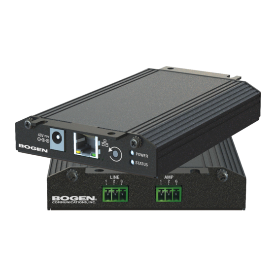
Nyquist integrated power amplifier
Hide thumbs
Also See for NQ-GA20P2:
- Installation and use manual (12 pages) ,
- Configuration manual (36 pages)

Related Manuals for Bogen NQ-GA20P2


Summary of Contents for Bogen NQ-GA20P2
- Page 1 Nyquist Integrated Power Amplifier Configuration Manual NQ-GA20P2 2019 Bogen Communications, Inc. All rights reserved. 740-00074A 191029...
-
Page 3: Table Of Contents
Contents List of Figures .......................v List of Tables ......................vii Configuring the Nyquist Integrated Power Amplifier..........1 Using the Dashboard................3 Updating Firmware ...................4 Setting Network Tab Parameters ............6 Setting Configuration Tab Parameters ..........8 Accessing Log Files................11 Setting DSP Parameters............... 15 Setting the Channel Level........... -
Page 5: List Of Figures
Figure 1, Nyquist Appliance Login ......2 Figure 2, NQ-GA20P2 Dashboard ......3 Figure 3, Firmware Update Page . -
Page 7: List Of Tables
List of Tables Table 1, Appliance Dashboard Read-Only Fields ....3 Table 2, Appliance Dashboard Buttons ..... . . 4 Table 3, Network Settings . - Page 8 viii...
-
Page 9: Configuring The Nyquist Integrated Power Amplifier
It also works in background music applications – leveraging the exhaustive audio management and distribution capabilities of Bogen’s Nyquist platform. The NQ-GA20P2 appliance uses the latest in Class D amplifier tech- nology and provides unparalleled sonic quality, exceptional reliability, and reduced power consumption to permit standalone PoE+ opera- tion over the local network. -
Page 10: Figure 1, Nyquist Appliance Login
To access the appliance’s UI: Step 1 Access the appliance’s web UI by doing one of the fol- lowing: a On your web browser, enter the IP address for the appliance as the URL. b From the Nyquist web UI navigation bar, select Sta- tions, select Stations Status, navigate to the device that you want to configure, and then select the Link icon. -
Page 11: Using The Dashboard
The dashboard for the selected appliance appears. Figure 2, NQ-GA20P2 Dashboard Using the Dashboard The dashboard displays the following read-only fields: Table 1, Appliance Dashboard Read-Only Fields Device Type Identifies the physical device used by the station. Serial Number Identifies the serial number for the device. -
Page 12: Updating Firmware
The dashboard also contains the following buttons: Table 2, Appliance Dashboard Buttons Dashboard Refreshes the dashboard. Configuration Set- Accesses the Configuration Settings page where you can either manually set various tings options, such as the SIP Username, or select to receive configuration settings from the server. -
Page 13: Figure 3, Firmware Update Page
required. You can also use this page to restore factory settings and to reboot the appliance. Note: A Nyquist appliance connected to the Nyquist network receives a config- uration file from the Nyquist server that includes the latest firmware available from the server. -
Page 14: Setting Network Tab Parameters
want to update the appliance’s firmware to the new version. Step 3 If you want to return your appliance to its original state (undoing firmware updates), select Restore Factory Settings. Step 4 Select Reboot Appliance to restart your appliance. Setting Network Tab Parameters Network settings can be configured dynamically by the Nyquist server or manually by using the appliance’s web UI. -
Page 15: Figure 4, Network Settings
Figure 4, Network Settings Network settings are described in the following table: Table 3, Network Settings Static IP Identifies the fixed IP address assigned to the appliance by a system administra- tor. Netmask Identifies the subnetwork subdivision of an IP network. Gateway Identifies the address, or route, for the default gateway. -
Page 16: Setting Configuration Tab Parameters
Table 3, Network Settings (Continued) VLAN Priority Identifies the priority of the network traf- fic on the VLAN. Priority can range from 0 through 7. NTP Server Identifies the IP address or the domain name of the Network Time Protocol (NTP) Server. - Page 17 tion From Server. However, you can manually configure an appliance through the appliance’s Web UI. Note: Manual configuration will be overwritten by the server once the appli- ance is connected and discovered by the server. To manually configure your Nyquist appliance: Step 1 On the appliance Web UI’s main page, select Configu- ration Settings.
-
Page 18: Figure 5, Appliance Configuration Settings
Figure 5, Appliance Configuration Settings The following table describes the Configuration tab settings:... -
Page 19: Accessing Log Files
Table 4, Configuration Settings Web Username Provide a web username for this appli- ance. Web Password Provide a web password for logging into the appliance. Web Confirm Pass- Re-enter the password used to log into the appliance. word SIP Username Provide the username used for Session Initiation Protocol (SIP) device registra- tion. -
Page 20: Figure 6, Logs
via download to your PC, Mac, or Android device and then copied to removable media or attached to an email to technical support. To view a log file: Step 1 On the appliance Web UI’s main page, select Logs. Step 2 From the drop-down menu, select the log that you want to view. -
Page 21: Table 5, Logs
Table 5, Logs Description alternatives.log Contains information by the update-alternatives, which maintain symbolic links determining default com- mands. ampws.log Contains information about protection status and logs protection events with temperature information at the time of event. auth.log Contains system authorization information, including user logins and authentication methods that were used. - Page 22 Table 5, Logs (Continued) Description wtmp Contains historical record of users logins at which ter- minals, logouts, system events, and current status of the system, and system boot time. wvdialconf.log Contains basic information about the modem port, speed, init string, and Internet Service Provider (ISP).
-
Page 23: Setting Dsp Parameters
Setting DSP Parameters When you select DSP from the appliances web UI, the DSP page appears. Figure 7, DSP Page with Channel Drop-Down Menu From this page, you can adjust settings in the DSP. The appliance uses traditional processors (for example, Compressor, Limiter) for audio signals in the digital domain. -
Page 24: Setting The Channel Level
Selecting the Menu button displays other parameters. DSP parame- ters and the Mute and Level buttons are described in the following table: Table 6, DSP Page Mute Silences the audio. Level Adjusts the channel volume leve in 1 dB increments. Compressor Lessens the dynamic range between the loudest and quietest parts of an audio signal. -
Page 25: Muting A Channel
Muting a Channel You can mute a channel to cut off an audio signal and stop the pro- duction of sound. To mute a channel: Step 1 On the appliance Web UI’s main page, select DSP. Step 2 Select the Mute button for the channel that you want to silence. -
Page 26: Table 7, Compressor Settings
Step 4 Make desired adjustments using the controls described in "Compressor Settings” on page 18. Note: If you want to return to the factory settings, select the Reset icon that appears in the right corner. Step 5 Select Enable to apply the settings to the selected channel. -
Page 27: Setting High Pass/Low Pass Parameters
Setting High Pass/Low Pass Parameters You can set the band of frequencies that will pass through the high pass and low pass filters and select the type of filter that is used through the channel’s High/Low Pass drop-down menu option. Figure 9, High/Low Pass Parameters To adjust the high/low pass parameters for a channel: Step 1... -
Page 28: Table 8, High Pass/Low Pass Parameters
Table 8, High Pass/Low Pass Parameters High Pass (Low Cut) This feature helps eliminate low frequency noise (signals of 100 Hz and below, such as background rumble from ventilation systems, etc.) and is used primarily with microphone level input. It is partic- ularly effective when hand held microphones are used. - Page 29 Table 8, High Pass/Low Pass Parameters (Continued) Low Pass (High Cut) This feature helps eliminate high frequency noise (signals of 8000 Hz and above) such as background hiss and sibilance (excessive "S" in vocals, etc.) and is used primarily with microphone level input. It is particularly effective when hand held microphones are used.
-
Page 30: Adjusting The Limiter
Adjusting the Limiter A limiter is a compressor with a high slope that is used to prevent a signal exceeding a set decibel level. Limiters are used as safeguards against signal clipping. Limiter parameters are set per channel. Figure 10, Limiter Settings To adjust the limiter settings for a channel: Step 1 On the appliance Web UI’s main page, select DSP. -
Page 31: Adjusting Outputs
Table 9, Limiter Settings (Continued) Decay Sets the rate for turn off of the limiter after the signal is below the threshold. Decay range is 5 to 2300 milliseconds. RMSTC Sets how fast the limiter reacts to the above threshold signal. RMSTC range is 50 to 10000. -
Page 32: Adjusting Parametric Equalizer Settings
Step 5 Make desired Volume adjustments by adjusting the knob. Volume levels range from -15 to 0 for the Speaker Output and -15 to 15 for the Line Output. Adjusting Parametric Equalizer Settings A parametric equalizer is a multi-band variable equalizer that allows control of frequency amplitude (boost/cut), center frequency, and frequency bandwidth, or Q. - Page 33 Step 4 Adjust frequencies as desired, ensuring the Enable LEDs are green for each selected frequency. You can adjust the frequencies by moving the Freq knob or by double-clicking the knob and typing the frequency. When typing the frequency, only numeric values from 20 to 20,000 can be entered.
-
Page 34: Settings
Settings You can set select a name and a color for the input channel. Figure 13, Settings Parameters To adjust the settings for the channel: Step 1 On the appliance Web UI’s main page, select DSP. Step 2 Select the Menu button for the channel. Step 3 From the drop-down menu, select Settings. -
Page 35: Signal Present
Signal Present You can set parameters for when a channel accepts a signal. You can set specific parameters for each input channel and for the output channel. Figure 14, Signal Present Parameters To adjust the Signal Present settings for a channel: Step 1 On the appliance Web UI’s main page, select DSP. -
Page 36: Table 10, Signal Present Parameters
Step 4 Adjust the following settings as needed. Table 10, Signal Present Parameters Threshold Sets the threshold level, or at what level the Signal LED is illuminated. Hold Sets the number of milliseconds that the sig- nal light stays on after the signal is no longer present.
Need help?
Do you have a question about the NQ-GA20P2 and is the answer not in the manual?
Questions and answers