
Related Manuals for Bogen NQ-P0100


Summary of Contents for Bogen NQ-P0100
- Page 1 Nyquist Matrix Mixer Pre-Amp Configuration Guide NQ-P0100 © 2021 Bogen Communications, Inc. All rights reserved. 740-00022F 210419...
-
Page 2: Table Of Contents
Contents Contents ............ii List of Figures . -
Page 3: List Of Figures
List of Figures Figure 1. Nyquist Appliance Login..........1 Figure 2. - Page 4 List of Tables Table 1, Appliance Dashboard Fields......... . 2 Table 2, Appliance Dashboard Buttons .
-
Page 5: Configuring The Nyquist Matrix Mixer Pre-Amp
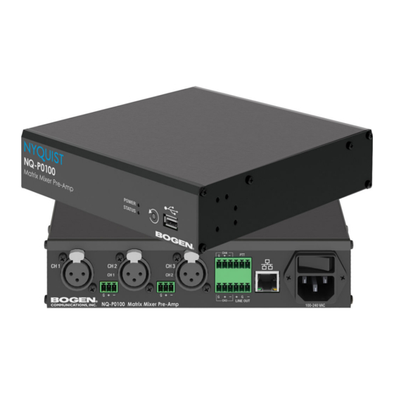
Configuring the Nyquist Matrix Mixer Pre-Amp The Nyquist Matrix Mixer Pre-Amp (NQ-P0100) is a mixer preamplifier that allows micro- phone, AES3 digital, and line-level source inputs to be integrated into a Nyquist system. These input sources can then be routed to any endpoint or group of endpoints on the network for paging or audio distribution. -
Page 6: Using The Dashboard
At the Nyquist Appliance Login page, enter username and password, and then select Login. The default username is admin; the default password is bogen. The dashboard for the selected appliance appears. Figure 2. Matrix Mixer Pre-Amp Dashboard Using the Dashboard The dashboard displays the following fields: Table 1. -
Page 7: Standalone Operation
• Store backup information to Nyquist server • Allow access to Nyquist server-based NTP Standalone Operation mode is ideal for scenarios that do not require the full functionality provided by an integrated system, such as the Bogen C4000 or E7000 Series, but has the... -
Page 8: Updating Firmware
ability to provide paging, multi-channel audio processing, and a SIP endpoint for a PBX/ VoIP phone system. It can be used to play music, audio, paging, and related functions. Updating Firmware When you select Firmware Update from the appliance’s web UI, the Firmware Update page appears. -
Page 9: Network Settings Tab Parameters
select Upload. The page displays the uploaded firmware version and an Update Firmware button appears. Select this button if you want to update the appliance’s firmware to the uploaded version. If you want to return your appliance to its original configuration, select Restore Fac- tory Settings. -
Page 10: Figure 4, Network Settings
Figure 4, Network Settings Network settings are described in the following table: Table 3, Network Settings Static IP Identifies the IP address assigned to the appliance. Netmask Identifies the subnetwork subdivision of an IP net- work. Gateway Identifies the address, or route, for the default gate- way. - Page 11 Table 3, Network Settings (Continued) NTP Server Identifies the IP address or the domain name of the Network Time Protocol (NTP) Server. Note: This field is only editable when Standalone Operation is enabled. TFTP Server Identifies the host name or IP address of the Trivial File Transfer Protocol (TFTP) server.
-
Page 12: Configuration Settings Tab Parameters
Table 3, Network Settings (Continued) DHCP Enabled Indicates if the device is enabled to use DHCP to retrieve its IP configuration. Reboot Appliance Indicates that this appliance should reboot when the Save button is clicked. Configuration Settings Tab Parameters The easiest way to configure Nyquist appliances is to obtain configuration settings from the Nyquist server by selecting Get Configuration From Server. -
Page 13: Figure 5. Appliance Configuration Settings (Standalone Disabled)
Figure 5. Appliance Configuration Settings (Standalone disabled) -
Page 14: Table 4, Configuration Settings (Standalone Disabled)
The following table describes the Configuration Settings tab settings: Table 4. Configuration Settings (Standalone disabled) Get Configuration from Retrieves configuration settings (i.e., web username, server, and local port) from the TFTP server specified in Server the Network Settings (see Table 1 on page 1). Web Username Provide a web username for this appliance. -
Page 15: Standalone Operation Configuration Settings
Account ID Shows the SIP account (IP address) associated with the device preceded by the extension of the device associ- ated with this port. Local Port Shows the port used for SIP. Username Shows the username or extension for the station associ- ated with the port. -
Page 16: Table 5, Configuration Settings (Standalone Enabled)
The following table describes the Configuration tab settings when Standalone Operation is enabled for this device: Table 5. Configuration Settings (Standalone enabled) Device Type Displays the type of this device. Device Name Provide a name for this device. Web Username Provide a web username for this appliance. - Page 17 Table 5. Configuration Settings (Standalone enabled) SIP Extension Specify the SIP extension corresponding to the Line Out channel. The extension, along with the IP address, is used to specify the URI used to place a SIP call to this extension: sip:<extension>@<local_ip_address>...
- Page 18 The following parameters appear for each Multicast Address configured for this device. Multicast IP Address The multicast IP address on which to receive audio streams. Multicast Port Number The multicast port on which to receive audio streams. Codec The codec to be used when decoding audio. Select one of the following values: •...
-
Page 19: Accessing Log Files
Accessing Log Files A log file records events and messages that occur when software runs, to be used when troubleshooting the appliance. From the appliance’s web-based UI, log files can be viewed directly or exported via download to your PC, Mac, or Android device, where they can be copied to removable media or attached to an email for technical support. -
Page 20: Table 6, Logs
Available logs are described in the following table. If a log file is empty, however, it will not appear in the drop-down list of available logs. Table 6, Logs Description ampws.log Contains information about protection status and logs protection events with temperature information at the time of event. -
Page 21: Setting Dsp Parameters
Setting DSP Parameters When you select DSP (Digital Signal Processing) from the appliance’s web UI, the DSP page appears. This page presents a mixing board interface, allowing you to monitor, con- trol, and perform DSP operations on the signal of the input and output channels. Note: Digital Signal Processing (DSP) refers to the digital operations that are performed to modify or control the digital signal. - Page 22 Figure 8. DSP Page The DSP page displays a mixing board console containing five input strips and one output strip. Each strip controls the audio signal for a given channel, providing muting, input/output levels, signal processing, and more. Signal processing includes traditional audio processing, such as compressors, noise gates, equalizers, and more.
- Page 23 • Adjust Input Gain level for each analog input channel. (See "Selecting Input Type, Input Gain, and Phantom Power” on page 22.) • Control Phantom Power for any channel using Mic as the input. (See "Selecting Input Type, Input Gain, and Phantom Power” on page 22.) Selecting the DSP Features button at the top-right corner of a channel displays a menu of DSP features for that channel.
-
Page 24: Table 8, Dsp Features
Table 7. DSP Page Line/AES/Mic Determines whether the input signal coming from the channel’s input jack is at line or microphone level, or if it is encoded as a digital AES signal. Phantom Power Determines if phantom power is being provided to the input microphone. -
Page 25: Setting The Channel Level
You can set Limiter and Signal Present parameters for the output signal or set global Ducker, Router, and Settings options by selecting the option you want from the drop- down menu available for the output. Figure 9. DSP Output Options Setting the Channel Level The Channel Level control is a vertical slider that is adjusted in 1 dB increments and con- trols the output level for the channel. -
Page 26: Muting A Channel
Muting a Channel You can mute a channel to cut off an audio signal and stop the input signal from being sent to the output channel. Note the input signal will still be visible on the IN meter, but the OUT meter will show that nothing is being forwarded to the output channel. To mute a channel: On the appliance Web UI’s main page, select DSP. -
Page 27: Troubleshooting Gain Structure
Note: Phantom power is only used by devices that contain active electronics, such as con- denser microphones and many direct boxes. It uses a balanced signal, which renders it effectively invisible to balanced microphones that do not use it. When enabled, +15V of balanced phantom power is available on pins 2 and 3 of the XLR connector or the +/- ter- minals of the Phoenix connector. -
Page 28: Adjusting Compression Settings
If the signal cannot be increased with the Input Gain knob at 2–3 o'clock, make sure the input is not set to Line. Note: Some microphones are very low output. The mixer will not be able to completely compensate for the low level but will be able to provide a usable output signal. A decent dynamic microphone output level is approximately -55 dB. -
Page 29: Table 9, Compressor Settings
To adjust the compressor settings for a channel: On the appliance Web UI’s main page, select DSP. Select the Menu button for the channel. From the drop-down menu, select Compressor. Make desired adjustments using the controls described in Table 9, “Compressor Set- tings,”... -
Page 30: Adjusting Ducking Settings
Table 9. Compressor Settings Knee Sets how far below the threshold compression will begin to be gradually applied to the signal. A very low value, known as a hard knee, immediately applies full compres- sion once the threshold is reached. A high value, known as a soft knee, will gradually start applying compression before the signal reaches the threshold, not reaching the full effect until the threshold is reached, thereby... -
Page 31: Figure 11. Ducker Parameters
reduction in the output of the music signal for the duration of the page. The ducker restores the original level for the background music once the page is over. Figure 11. Ducker Parameters To adjust the ducker settings for a channel: On the appliance Web UI’s main page, select DSP. -
Page 32: Adjusting The Graphic Equalizer
Table 10. Ducker Parameters Master Select the channel that serves as the master, or unducked, channel. The audio on this channel has priority; audio for all other channels is ducked. Ducked Select the channel or channels that will be ducked when the threshold is reached on the master channel. -
Page 33: Setting High Pass/Low Pass Parameters
By default, each knob is set at 0 dB, which means that no frequencies are being boosted or cut. Note: For the best results, frequencies should be cut only. Boosting frequencies to com- pensate for room dimensions or speaker response deficiencies usually results in a loss of headroom in the signal chain. -
Page 34: Figure 13. High/Low Pass Parameters
You can specify the range of frequencies that will pass through the high pass and low pass filters and select the type of filter that is used through the channel’s High/Low Pass drop-down menu option. Figure 13. High/Low Pass Parameters To adjust the high/low pass parameters for a channel: On the appliance Web UI’s main page, select DSP. -
Page 35: Table 11, High Pass/Low Pass Parameters
Table 11. High Pass/Low Pass Parameters High Pass (Low Cut) This feature helps eliminate low frequency noise (signals of 100 Hz and below, such as background rumble from ventilation systems, etc.) and is used primarily with micro- phone level input. It is particularly effective when hand held microphones are used. Frequency Set the cutoff frequency. -
Page 36: Adjusting The Limiter
Table 11. High Pass/Low Pass Parameters (Continued) Low Pass (High Cut) This feature helps eliminate high frequency noise (signals of 8000 Hz and above) such as background hiss and sibilance (excessive "S" in vocals, etc.) and is used primarily with microphone level input. It is particularly effective when handheld microphones are used. -
Page 37: Figure 14. Limiter Settings
Limiter parameters are set per channel. Figure 14. Limiter Settings To adjust the limiter settings for a channel: On the appliance Web UI’s main page, select DSP. Select the Menu button for the channel or select the Menu button for the Output. From the drop-down menu, select Limiter. -
Page 38: Table 12, Limiter Settings
Table 12. Limiter Settings Threshold Sets the signal level at which the limiter is triggered. Any signal exceeding this threshold will be compressed to this level. The range is -24 to +24 dB. Decay Sets the rate for turn off of the limiter after the signal is below the threshold. -
Page 39: Adjusting Noise Gate Settings
Adjusting Noise Gate Settings A noise gate controls the volume of an audio signal by attenuating the signal when it reg- isters below the threshold. This is typically used to eliminate or minimize background noise. Figure 15. Noise Gate Settings To adjust the noise gate settings for a channel: On the appliance Web UI’s main page, select DSP. -
Page 40: Table 13, Noise Gate Settings
Table 13. Noise Gate Settings Enable Enables or disables the noise gate DSP effect for this chan- nel. Threshold Sets the minimum threshold level that the signal must reach for the noise gate to “open”, allowing the signal to be sent to the output channel. Threshold range is -135 to +21 db. -
Page 41: Adjusting Parametric Equalizer Settings
Adjusting Parametric Equalizer Settings A parametric equalizer is a multi-band variable equalizer that allows control of frequency amplitude (boost/cut), center frequency, and frequency bandwidth, or Q. Figure 16. Parametric Equalizer Settings The parameter equalizer settings for your device allows you to adjust the Q and gain for seven separate frequencies, which then become plot points on the screen’s graph. -
Page 42: Adjusting Router Settings
Q is the Quality or Quality Factor, which refers to the bandwidth of one band of a parametric equalizer. Q is calculated by dividing the center frequency in Hz by the width of the boost or cut zone, +3 dB or -3 dB above or below 0 dB. For each frequency, use the Gain knob or double-click the knob and type the gain to either boost (turn up) or cut (turn down). -
Page 43: Figure 17. Router Settings
Figure 17. Router Settings To adjust the router settings: On the appliance Web UI’s main page, select DSP. Select the Menu button for the channel or select the Menu button for the Output. From the drop-down menu, select Router. Note: If you want to return to the factory settings, select the Reset icon that appears in the right corner. -
Page 44: Settings
Signals from input channels Analog 1 to 4 can be mixed to each output as desired. Multiple input signals can be mixed to multiple outputs or to a single output. Like- wise, outputs are enabled by selecting the Enable button for the selected outputs (turning the button from gray to green). - Page 45 From the drop-down menu, select Settings. Note: If you want to return to the factory settings, select the Reset icon that appears in the right corner. For each channel, type the name that you want to display for the channel. For each channel, select a color that will be used to highlight the channel.
-
Page 46: Signal Present
Signal Present You can configure the threshold level that a signal must reach before the Signal LED is lit, as well as how long the LED will remain lit. You can configure this for each input channel and for the output channel. Figure 19. -
Page 47: Table 14, Signal Present Parameters
Adjust the following settings as needed. Table 14. Signal Present Parameters Threshold Sets the minimum level the signal must reach before the Signal LED is illuminated. Hold Sets the minimum number of milliseconds that the Signal LED will remain illuminated.
Need help?
Do you have a question about the NQ-P0100 and is the answer not in the manual?
Questions and answers