Bogen Nyquist NQ-P0100 Configuration Manual
Matrix mixer pre-amp
Hide thumbs
Also See for Nyquist NQ-P0100:
- Installation manual (6 pages) ,
- Configuration manual (47 pages)

Related Manuals for Bogen Nyquist NQ-P0100


Summary of Contents for Bogen Nyquist NQ-P0100
- Page 1 Nyquist Matrix Mixer Pre-Amp Configuration Manual 2019 Bogen Communications, Inc. All rights reserved. 740-00022F 190215...
-
Page 3: Table Of Contents
Contents List of Figures .......................v List of Tables ......................vii Configuring the Nyquist Matrix Mixer Pre-Amp ............1 Using the Dashboard................3 Updating Firmware ...................4 Setting Network Tab Parameters ............6 Setting Configuration Tab Parameters ..........9 Accessing Log Files................11 Setting DSP Parameters............... 14 Setting the Channel Level........... -
Page 5: List Of Figures
List of Figures Figure 1, Nyquist Appliance Login ......2 Figure 2, Matrix Mixer Pre-Amp Dashboard ....2 Figure 3, Firmware Update Page . -
Page 7: List Of Tables
List of Tables Table 1, Appliance Dashboard Read-Only Fields ....3 Table 2, Appliance Dashboard Buttons ..... . . 3 Table 3, Network Settings . - Page 8 viii...
-
Page 9: Configuring The Nyquist Matrix Mixer Pre-Amp
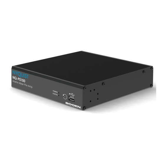
Configuring the Configuring the Nyquist Matrix Nyquist Matrix Mixer Pre-Amp The Nyquist Matrix Mixer Pre-Amp (NQ-P0100) is a mixer pre-ampli- fier that allows microphone, AES3 digital, and line-level source inputs to be integrated into a Nyquist system. These input sources can then be routed to any endpoint or group of endpoints on the network for paging or audio distribution. -
Page 10: Figure 1, Nyquist Appliance Login
Step 2 At the Nyquist Appliance - Login page, enter username and password, and then select Login. The default username is admin; the default password is bogen. The dashboard for the selected appliance appears. Figure 2, Matrix Mixer Pre-Amp Dashboard... -
Page 11: Using The Dashboard
Using the Dashboard The dashboard displays the following read-only fields: Table 1, Appliance Dashboard Read-Only Fields Device Type Identifies the physical device used by the station. Serial Number Identifies the serial number for the device. MAC Address Specifies the Media Access Control (MAC) address, which is a unique identifier assigned to network interfaces for communications on the physical network... -
Page 12: Updating Firmware
Table 2, Appliance Dashboard Buttons Logs Accesses log files, which record either events or messages that occur when soft- ware runs and are used when trouble- shooting the appliance. Accesses the DSP page where you can view and set parameters for Digital Signal Pro- cessing (DSP). -
Page 13: Figure 3, Firmware Update Page
Figure 3, Firmware Update Page To use the Firmware Update page: Step 1 On the appliance web UI’s main page, select Firmware Update to ensure you have the latest firmware version. Step 2 Select Upload Firmware to upload firmware from the server to the appliance. -
Page 14: Setting Network Tab Parameters
Setting Network Tab Parameters Network settings can be configured dynamically by the Nyquist server or manually by using the appliance’s web UI. To manually configure network settings: Step 1 On the appliance web UI’s main page, select Network Settings. Step 2 Select your desired network settings. -
Page 15: Figure 4, Network Settings
Figure 4, Network Settings... -
Page 16: Table 3, Network Settings
Network settings are described in the following table: Table 3, Network Settings Static IP Identifies the fixed IP address assigned to the appliance by a system administra- tor. Netmask Identifies the subnetwork subdivision of an IP network. Gateway Identifies the address, or route, for the default gateway. -
Page 17: Setting Configuration Tab Parameters
Table 3, Network Settings DHCP Enabled Indicates if the device is enabled to use DHCP. Reboot Appliance Allows you to save the network options and reboot the appliance. Setting Configuration Tab Parameters The easiest way to configure Nyquist appliances is to obtain configu- ration settings from the Nyquist server by selecting Get Configura- tion From Server. -
Page 18: Figure 5, Appliance Configuration Settings
Figure 5, Appliance Configuration Settings The following table describes the Configuration tab settings: Table 4, Configuration Settings Web Username Provide a web username for this appli- ance. Web Password Provide a web password for logging into the appliance. Web Confirm Pass- Re-enter the password used to log into the appliance. -
Page 19: Accessing Log Files
Table 4, Configuration Settings (Continued) SIP Username Provide the username used for Session Initiation Protocol (SIP) device registra- tion. SIP Password Provide the password used for SIP device registration. SIP Confirm Pass- Re-enter the password used for SIP device registration. word Server Identifies the IP address of the Nyquist... -
Page 20: Figure 6, Logs
To view a log file: Step 1 On the appliance Web UI’s main page, select Logs. Step 2 From the drop-down menu, select the log that you want to view. Multiple versions of the same log and zipped copies of the log may be available. -
Page 21: Table 5, Logs
Table 5, Logs Description alternatives.log Contains information by the update-alternatives, which maintain symbolic links determining default com- mands. auth.log Contains system authorization information, including user logins and authentication methods that were used. bootstrap.log Contains information actions, errors, and warnings that occur during booting of the appliance. -
Page 22: Setting Dsp Parameters
Table 5, Logs Description wtmp Contains historical record of users logins at which ter- minals, logouts, system events, and current status of the system, and system boot time. wvdialconf.log Contains basic information about the modem port, speed, init string, and Internet Service Provider (ISP). Setting DSP Parameters When you select DSP from the appliance’s web UI, the DSP page appears. -
Page 23: Table 6, Dsp Page
From this page, you can adjust settings in the DSP. The appliance uses traditional processors (for example, Compressor, Noise Gate, Graphic Equalizer) for audio signals in the digital domain. The DSP page shows Mute and Level selections for four input chan- nels and allows you to do the following: •... - Page 24 Table 6, DSP Page (Continued) High/Low Pass Sets the band of frequencies that will pass through the high pass and low pass filters and select the type of filter that is used. Limiter Prevents a signal from exceeding an adjust- able maximum level.
-
Page 25: Setting The Channel Level
ing the option you want from the drop-down menu available for the output. Figure 8, DSP Output Options Setting the Channel Level The Channel Level control is a vertical slider that is adjusted in 1 dB increments and that controls the input or output levels to and from the mixer. -
Page 26: Muting A Channel
The VU meter not only illuminates green, yellow, or red (depending on the signal level) but also has a scale ranging from +12 dB to -60 dB to help you indicate the actual signal level. Muting a Channel You can mute a channel to cut off an audio signal and stop the pro- duction of sound. -
Page 27: Troubleshooting Gain Structure
the XLR connector. Phantom power cannot be enabled when Line input is selected. Troubleshooting Gain Structure Channel Sliders should be set to 0 dB (unity gain) during the channel level setup procedure. The range for optimal Input Gain control operation is from about 9 o’clock to 2 o'clock. -
Page 28: Adjusting Compression Settings
6.6.3 If Channel Volume Is Too High If a channel is not clipping but the channel slider level control must be set below the -20 dB position to achieve the proper volume level, the Input Gain control setting is too high. Set the channel slider con- trol knob to the 0 dB position and adjust the Input Gain control until the desired volume level is achieved. -
Page 29: Adjusting Ducking Settings
Note: Step 4 Make desired adjustments using the controls described If you want in "Compressor Settings” on page 21. to return to the factory settings, Step 5 Select Enable to apply the settings to the selected select the Reset channel. icon that appears in the right corner. -
Page 30: Figure 10, Ducker Parameters
page. The ducker restores the original level for the background music once the page is over. Figure 10, Ducker Parameters To adjust the ducker settings for a channel: Step 1 On the appliance Web UI’s main page, select DSP. Step 2 Select the Menu button for the channel or select the Menu button for the Output. -
Page 31: Adjusting The Graphic Equalizer
Table 8, Ducker Parameters Master Select the channel that serves as the master, or unducked, channel. The audio on this channel has priority; audio for all other chan- nels is ducked. Ducked Select the channel or channels that will be ducked when the threshold is reached on the master channel. -
Page 32: Setting High Pass/Low Pass Parameters
The Graphic EQ provides 16 slider knobs that can be moved between +12 dB and -12 dB. The frequency of each slider is different and range from 25 Hz to 20,000 (20k) Hz. By default, each knob is set at 0 dB, which means that no frequencies are being boosted or cut. -
Page 33: Table 9, High Pass/Low Pass Parameters
To adjust the high/low pass parameters for a channel: Step 1 On the appliance Web UI’s main page, select DSP. Step 2 Select the Menu button for the channel. Step 3 From the drop-down menu, select High/Low Pass. Note: Step 4 Set the parameters described in the following table: If you want to return to the... - Page 34 Table 9, High Pass/Low Pass Parameters (Continued) Low Pass (High Cut) This feature helps eliminate high frequency noise (signals of 8000 Hz and above) such as background hiss and sibilance (excessive "S" in vocals, etc.) and is used primarily with microphone level input. It is particularly effective when hand held microphones are used.
-
Page 35: Adjusting The Limiter
6.11 Adjusting the Limiter A limiter is a compressor with a high slope that is used to prevent a signal exceeding a set decibel level. Limiters are used as safeguards against signal clipping. Limiter parameters are set per channel. Figure 13, Limiter Settings To adjust the limiter settings for a channel: Step 1 On the appliance Web UI’s main page, select DSP. -
Page 36: Adjusting Noise Gate Settings
6.12 Adjusting Noise Gate Settings A noise gate controls the volume of an audio signal by attenuating by a fixed amount the signals that register below the threshold. Figure 14, Noise Gate Settings To adjust the noise gate settings for a channel: Step 1 On the appliance Web UI’s main page, select DSP. -
Page 37: Adjusting Parametric Equalizer Settings
Table 11, Noise Gate Settings Threshold Sets the threshold level that the signal must be below for the noise gate to “close” (pre- vent the sound from getting through). Threshold range is -135 to +21 db. Attack Adjusts how long it takes for the gate to open once the signal falls below the thresh- old. -
Page 38: Adjusting Router Settings
Step 3 From the drop-down menu, select Parametric EQ. The Parametric EQ provides seven slider knobs that can be moved between +12 dB and -12 dB. The frequency of each slider is can be adjusted from 20 Hz to 20,000 Hz. -
Page 39: Figure 16, Router Settings
drop-down menus of each channel, but only one router exists for the appliance. Figure 16, Router Settings To adjust the router settings: Step 1 On the appliance Web UI’s main page, select DSP. Step 2 Select the Menu button for the channel or select the Menu button for the Output. -
Page 40: Settings
Signals from Channels 1 to 4 can be mixed to each out- put as desired. Multiple input signals can be mixed to multiple outputs or to a single output. Likewise, outputs are enabled by selecting the Enable button for the selected outputs (turning the button from gray to green). -
Page 41: Signal Present
Step 5 For each channel, select a color that will be used to highlight the channel. Note: Step 6 Select Save. If you want to return to the factory settings, select the Reset icon that appears 6.16 Signal Present in the right corner. You can set parameters for when a channel accepts a signal. -
Page 42: Table 12, Signal Present Parameters
Note: Step 4 Adjust the following settings as needed. If you want to return to the Table 12, Signal Present Parameters factory settings, Threshold Sets the threshold level, or at what level the select the Reset Signal LED is illuminated. icon that appears in the right corner.
Need help?
Do you have a question about the Nyquist NQ-P0100 and is the answer not in the manual?
Questions and answers