
Related Manuals for Bogen NQ-A2060


Summary of Contents for Bogen NQ-A2060
- Page 1 2-Channel Audio Power Amplifiers Configuration Manual NQ-A2060, NQ-A2120, NQ-A2300 2019 Bogen Communications, Inc. All rights reserved. 740-00084E 191030...
-
Page 3: Table Of Contents
Contents List of Figures................v List of Tables ................vii Configuring the Two-Channel Audio Power Amplifiers ........... 1 Using the Dashboard ................3 Updating Firmware ..................4 Setting Network Tab Parameters ............5 Setting Configuration Tab Parameters ..........8 Accessing Log Files ................10 Setting DSP Parameters .............. -
Page 5: List Of Figures
List of Figures Figure 1, Nyquist Appliance Login ......2 Figure 2, Matrix Mixer Pre-Amp Dashboard ....2 Figure 3, Firmware Update Page . -
Page 7: List Of Tables
List of Tables Table 1, Appliance Dashboard Read-Only Fields ....3 Table 2, Appliance Dashboard Buttons ..... . . 3 Table 3, Network Settings . - Page 8 viii...
-
Page 9: Configuring The Two-Channel Audio Power Amplifiers
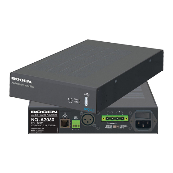
Channel Audio Audio Power Amplifiers Bogen’s Nyqust-based networked two-channel audio power amplifi- ers (NQ-A2060, NQ-A2120, NQ-A2300) support small, medium, and large Nyquist intercom solutions in schools and in commercial paging and public address solutions. Available in 120, 240 and 600-watt models, the audio power amplifi- ers provide flexibility and versatility without the need for add-on modules. -
Page 10: Figure 1, Nyquist Appliance Login
Step 2 At the Nyquist Appliance - Login page, enter username and password, and then select Login. The default username is admin; the default password is bogen. The dashboard for the selected appliance appears. Figure 2, Matrix Mixer Pre-Amp Dashboard... -
Page 11: Using The Dashboard
Using the Dashboard The dashboard displays the following read-only fields: Table 1, Appliance Dashboard Read-Only Fields Device Type Identifies the physical device used by the station. Serial Number Identifies the serial number for the device. MAC Address Specifies the Media Access Control (MAC) address, which is a unique identifier assigned to network interfaces for commu- nications on the physical network segment. -
Page 12: Updating Firmware
Table 2, Appliance Dashboard Buttons Help Accesses the appliance’s online help. Manual Displays the Nyquist Matrix Mixer Pre-Amp Configuration Manual. Logout Logs out of the appliance’s dashboard. Updating Firmware When you select Firmware Update from the appliance’s web UI, the Firmware Update page appears. -
Page 13: Setting Network Tab Parameters
To use the Firmware Update page: Step 1 On the appliance web UI’s main page, select Firmware Update to ensure you have the latest firmware version. Step 2 Select Upload Firmware to upload firmware from the server to the appliance. If you select this option, a popup screen appears that allows you to select the file that you want to upload. -
Page 14: Figure 4, Network Settings
Figure 4, Network Settings Network settings are described in the following table: Table 3, Network Settings Static IP Identifies the fixed IP address assigned to the appliance by a system administra- tor. Netmask Identifies the subnetwork subdivision of an IP network. Gateway Identifies the address, or route, for the default gateway. - Page 15 Table 3, Network Settings (Continued) VLAN Priority Identifies the priority of the network traf- fic on the VLAN. Priority can range from 0 through 7. NTP Server Identifies the IP address or the domain name of the Network Time Protocol (NTP) Server.
-
Page 16: Setting Configuration Tab Parameters
Setting Configuration Tab Parameters The easiest way to configure Nyquist appliances is to obtain configu- ration settings from the Nyquist server by selecting Get Configura- tion From Server. However, you can manually configure an appliance through the appliance’s Web UI. Note: Manual configuration will be overwritten by the server once the appli- ance is connected and discovered by the server. -
Page 17: Figure 5, Appliance Configuration Settings
Figure 5, Appliance Configuration Settings The following table describes the Configuration tab settings: Table 4, Configuration Settings Web Username Provide a web username for this appliance. Web Password Provide a web password for logging into the appliance. Web Confirm Pass- Re-enter the password used to log into the appliance. -
Page 18: Accessing Log Files
Table 4, Configuration Settings (Continued) Local Port Identifies the local port. Emergency-All-Call Identifies the IP address, port number, and volume used for emergency all-calls pages. All-Call Identifies the IP address, port number, and volume used for all-calls pages. Audio Distribution Identifies the IP address, port number, and volume used for audio distribution. -
Page 19: Figure 6, Logs
To view a log file: Step 1 On the appliance Web UI’s main page, select Logs. Step 2 From the drop-down menu, select the log that you want to view. Multiple versions of the same log and zipped copies of the log may be available. -
Page 20: Table 6, Logs
Table 6, Logs Description alternatives.log Contains information by the update-alternatives, which maintain symbolic links determining default com- mands. ampws.log Contains information about protection status and logs protection events with temperature information at the time of event. auth.log Contains system authorization information, including user logins and authentication methods that were used. -
Page 21: Setting Dsp Parameters
Table 6, Logs (Continued) Description wtmp Contains historical record of users logins at which ter- minals, logouts, system events, and current status of the system, and system boot time. wvdialconf.log Contains basic information about the modem port, speed, init string, and Internet Service Provider (ISP). Setting DSP Parameters When you select DSP from the appliance’s web UI, the DSP page appears. -
Page 22: Figure 8, Dsp For Single Channel Bridged Mode
From this page, you can adjust settings in the DSP. The appliance uses traditional processors (for example, Compressor, Noise Gate, Graphic Equalizer) for audio signals in the digital domain. Note that if your appliance is operating in single channel bridged mode, you will see only one Network channel. -
Page 23: Setting The Channel Level
DSP parameters and the Mute and Level buttons are described in the following table. Table 7, DSP Page Mute Silences the audio for the selected channel. Level Adjusts the channel volume level in 1 dB increments. Compressor Lessens the dynamic range between the loudest and quietest parts of an audio signal. -
Page 24: Signal Led, Clip Led, And Vu Meter
place the mouse over the slider, the numerical value of the level appears. Signal LED, Clip LED, and VU Meter To the right of the Channel Level control are the Signal and Clip LEDs and the VU meter. The green Signal LED automatically illuminates when a signal is being received. -
Page 25: Adjusting Compression Settings
See also: • "Using the Dashboard” on page 3 • "Updating Firmware” on page 4 • "Setting Network Tab Parameters” on page 5 • "Setting Configuration Tab Parameters” on page 8 • "Accessing Log Files” on page 10 Adjusting Compression Settings A compressor slightly reduces the dynamic range of a signal. -
Page 26: Adjusting The Graphic Equalizer
Step 4 Make desired adjustments using the controls described in "Compressor Settings” on page 18. Note: If you want to return to the factory settings, select the Reset icon that appears in the right corner. Step 5 Select Enable to apply the settings to the selected channel. -
Page 27: Figure 10, Graphic Eq Settings
audio signal frequency content to optimize the frequency response of the sound system. The graphic equalizer parameters are set per channel. Figure 10, Graphic EQ Settings To adjust the graphic equalizer settings for a channel: Step 1 On the appliance Web UI’s main page, select DSP. Step 2 Select the Menu button for the channel. -
Page 28: Setting High/Low Pass Parameters
Setting High/Low Pass Parameters You can set the band of frequencies that will pass through the high pass and low pass filters and select the type of filter that is used through the channel’s High/Low Pass drop-down menu option. Figure 11, High/Low Pass Parameters To adjust the high/low pass parameters for a channel: Step 1 On the appliance Web UI’s main page, select DSP. -
Page 29: Table 9, High Pass/Low Pass Parameters
Table 9, High Pass/Low Pass Parameters High Pass (Low Cut) This feature helps eliminate low frequency noise (signals of 100 Hz and below, such as background rumble from ventilation systems, etc.) and is used primarily with microphone level input. It is partic- ularly effective when hand held microphones are used. - Page 30 Table 9, High Pass/Low Pass Parameters (Continued) Low Pass (High Cut) This feature helps eliminate high frequency noise (signals of 8000 Hz and above) such as background hiss and sibilance (excessive "S" in vocals, etc.) and is used primarily with microphone level input. It is particularly effective when hand held microphones are used.
-
Page 31: Adjusting The Limiter
Adjusting the Limiter A limiter is a compressor with a high slope that is used to prevent a signal exceeding a set decibel level. Limiters are used as safeguards against signal clipping. Limiter parameters are set per channel. Figure 12, Limiter Settings To adjust the limiter settings for a channel: Step 1 On the appliance Web UI’s main page, select DSP. -
Page 32: Adjusting Noise Gate Settings
Table 10, Limiter Settings (Continued) Decay Sets the rate for turn off of the limiter after the signal is below the threshold. Decay range is 5 to 2300 milliseconds. RMSTC Sets how fast the limiter reacts to the above threshold signal. RMSTC range is 50 to 10000. -
Page 33: Adjusting Parametric Equalizer Settings
Step 4 Adjust the following settings as needed: Table 11, Noise Gate Settings Threshold Sets the threshold level that the signal must be below for the noise gate to “close” (pre- vent the sound from getting through). Threshold range is -135 to +21 db. Attack Adjusts how long it takes for the gate to open once the signal falls below the thresh-... - Page 34 The parameter equalizer settings for your device allows you to adjust the Q and gain for seven separate frequencies, which then become plot points on the screen’s graph. To adjust the parametric equalizer settings for a channel: Step 1 On the appliance Web UI’s main page, select DSP. Step 2 Select the Menu button for the channel.
-
Page 35: Adjusting Router Settings
6.11 Adjusting Router Settings Router settings allow you to specify where to output a signal. For example, you could have two speakers attached to the power ampli- fier that is operating in 2-channel mono mode and only want to route the signal to the first speaker. -
Page 36: Settings
Step 4 Use the Enable button to select the output. 6.12 Settings You can set select names and colors for each of the input channels. Note that if your appliance is configured for single channel bridge mode, only one Network input channel appears. Figure 17, Settings Parameters for 2 Channel Mono... -
Page 37: Figure 18, Settings Parameters For Single Channel Bridged
Figure 18, Settings Parameters for Single Channel Bridged To adjust the settings for a channel: Step 1 On the appliance Web UI’s main page, select DSP. Step 2 Select the Menu button for the channel. Step 3 From the drop-down menu, select Settings. Note: If you want to return to the factory settings, select the Reset icon that appears in the right corner. -
Page 38: Signal Present
6.13 Signal Present You can set parameters for when a channel accepts a signal. You can set specific parameters for each input channel and for the output channel. Figure 19, Signal Present Parameters To adjust the Signal Present settings for a channel: Step 1 On the appliance Web UI’s main page, select DSP. -
Page 39: Status
Step 4 Adjust the following settings as needed. Table 12, Signal Present Parameters Threshold Sets the threshold level, or at what level the Signal LED is illuminated. Hold Sets the number of milliseconds that the sig- nal light stays on after the signal is no longer present. -
Page 40: Figure 21, Status For Bridged Channel
Figure 21, Status for Bridged Channel To view status for the power amplifier: Step 1 On the appliance Web UI’s main page, select DSP. Step 2 Select the Menu button for the channel. -
Page 41: Table 13, Status
Step 3 From the drop-down menu, select Status. The view only information that appears is described in the following table: Table 13, Status Switch Position Indicates the position of the Amplifier Mode switch located on the rear of the appliance. Bridged mode is typically used when higher power, single channel operation with a high impedance loudspeaker load is needed.
Need help?
Do you have a question about the NQ-A2060 and is the answer not in the manual?
Questions and answers