Advertisement
Table of Contents
- 1 Controls and Components
- 2 Control Panel
- 3 Combustion Chamber
- 4 Maintenance Schedule
- 5 Repair Procedures
- 6 Fuel Filter Assembly
- 7 Fuel Pump Assembly
- 8 Electric Panel Assembly
- 9 Air Pressure Switch
- 10 Combustion Chamber Assembly
- 11 Troubleshooting Guide
- 12 Wiring Diagram
- 13 Technical Specifications
- Download this manual
DIESEL SPACE HEATER-SERVICE MANUAL
INDEX
1. CONTROLS AND COMPONENTS
2. FLAME CONTROL CYCLES
3. MAINTENANCE SCHEDULE
4. REPAIR PROCEDURES
1. FAN MOTOR ASSEMBLY
2. FUEL FILTER ASSEMBLY
3. FUEL PUMP ASSEMBLY
4. ELECTRIC PANEL ASSEMBLY
5. AIR PRESSURE SWITCH
6. COMBUSTION HEAD ASSEMBLY
7. COMBUSTION CHAMBER
5. TROUBLESHOOTING GUIDE
6. WIRING DIAGRAMS
7. TECHNICAL SHEETS
The operations described in this booklet must be carried out by qualified and instructed personnel only.
Incorrect maintenance may result in improper operation and serious injury.
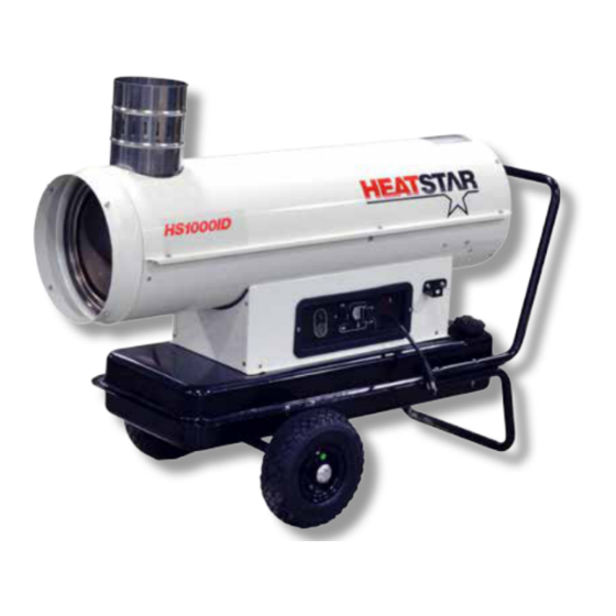
HS1000ID
WARNING
1
L-S 101.00-BM
Advertisement
Table of Contents

Subscribe to Our Youtube Channel
Related Manuals for Enerco HEATSTAR HS1000ID


Summary of Contents for Enerco HEATSTAR HS1000ID
- Page 1 DIESEL SPACE HEATER-SERVICE MANUAL INDEX 1. CONTROLS AND COMPONENTS 2. FLAME CONTROL CYCLES 3. MAINTENANCE SCHEDULE 4. REPAIR PROCEDURES 1. FAN MOTOR ASSEMBLY 2. FUEL FILTER ASSEMBLY 3. FUEL PUMP ASSEMBLY 4. ELECTRIC PANEL ASSEMBLY 5. AIR PRESSURE SWITCH 6. COMBUSTION HEAD ASSEMBLY 7.
-
Page 2: Controls And Components
1. CONTROLS AND COMPONENTS HS1000ID INDIRECT HEATER WITH STACK AND METAL FUEL TANK: 1 COMBUSTION CHAMBER 2 BURNER ASSEMBLY 3 NOZZLE 4 FUEL VALVE 5 DIESEL PUMP 6 MOTOR 7 FAN 8 FUEL FILTER 9 FUEL CIRCUIT 10 FUEL TANK 11 FUEL TANK PLUG 12 DRAIN PLUG 13 RESET BUTTON/LAMP OF... -
Page 3: Combustion Chamber
CONTROL SYSTEM The heater has all operational controls located in a watertight control panel mounted on a lateral side of the unit (EC 100) or rear side of the unit (EC 100PT). The control panel consists of: • a 3-position switch for heating function: normal operation, stop or thermostat operation • plug to connect a remote room thermostat • power cord • control flame box to handle starting / running cycle (see paragraph 2.). - Page 4 2. FLAME CONTROL RUNNING / FAILURE CYCLE 2.1 STARTING CYCLE Room thermostat Burner Fan Ignition Transformer Fuel Valve Photocell Reset Lamp TS 5 s TP 20 s The flame control unit starts the sequence of operation after a heating request (normal operation or thermostat operation) and it consists of the following steps: • Self-test (less than 3 s): self-check of electronics efficiency; • Purging time TP (20 seconds): fan motor and ignition transformer are simultaneously switched on while the fuel valve remains closed to eliminate any fuel or unburnt residual. During the purging stage, the flame signal is constantly monitored for any kind of failure leading to combustion prevents the burner ignition. In case of heating request off (room thermostat off), the control unit goes to stand-by position. The device remains in this status till closing of the room thermostat;...
- Page 5 2.3 FLAME FAILURE DURING STARTING CYCLE Room thermostat Burner Fan Ignition Transformer Fuel Valve Photocell Reset Lamp TS 5 s TP 20 s If during the safety time TS, the photocell monitors a flame failure (signal to photocell becomes lower than minimum), at the end of safety time the unit goes in lock out condition: • burner fan, ignition transformer and fuel valve are de-energized; • alarm lamp on rest button becomes red Unit can re-start only if pressing the reset button (3 seconds) 2.4 EXTRANEOUS LIGHT OR FLAME DURING PRE-PURGE TIME TP Room thermostat Burner Fan Ignition Transformer Fuel Valve Photocell...
- Page 6 2.5 FLAME FAILURE DURING RUNNING STATUS (ONE TRIAL RECYCLING) Room thermostat Burner Fan Ignition Transformer Fuel Valve Photocell Reset Lamp TP 20 s TS 5 s 90 s In case of flame failure in running status, the flame control unit make one trial restarting the unit. If the reason of flame failure is confirmed, then the unit stops in lock-out mode, and the reset lamp becomes red. 2.6 RESET LAMP COLOR WARNING The reset button may have different colours: • light off: unit is in stand-by status, waiting for heating request. • steady orange light : the heater stops temporarily to allow H/T/ transformer cooling down and automatically restarts when the time has passed •...
-
Page 7: Maintenance Schedule
3. MAINTENANCE SCHEDULE Periodic maintenance of the heater is necessary to ensure proper performance and to prevent failures and it shall be performed at the following periodic intervals: • Daily maintenace i. Inspect air inlet / air outlet and exhaust stack, remove debris if any ii. If any air hose is installed, secure it. Minimize bends and keeps ducts straight iii. Verify fuel tank is full iv. Verify that exhaust stack is properly installed • Weekly maintenance i. Disassemble, inspect and clean fuel filter with clean fuel ii. Remove top cover and clean the motor, fan blade and the interior shell iii. Inspect the fuel hose assembly and check for any leaks • 6 months maintenance i. Disassemble burner head 1. Inspect and clean burner diffuser 2. Inspect and replace nozzle as necessary 3. Clean ignition electrodes and adjust settings 4. Check air combustion setting ii. Check overheat thermostat iii. Inspect and clean the combustion chamber iv. Open electric board, inspect electrical components and check connections v. Check fuel pressure setting of fuel pump vi. Inspect and test the burner... -
Page 8: Repair Procedures
4. REPAIR PROCEDURES WARNING Before carrying out any maintenance operation the heater must be disconnected from power supply. Refer to instruction manual to fully stop the heater. Therefore: • Stop the machine as instructed • Turn off the on/off switch on the main electric switchboard •... -
Page 9: Fuel Filter Assembly
b) To replace the fan blade and the electric motor, carry out the following procedure. i) Remove the air inlet grille (a) by removing four screws that secure it to the machine. ii) Loosen the screw (d) on the fan hub iii) Extract the fan blades and replace with a new one respecting blades orientation iv) Remove the top cover access panel (b) by removing screws v) Loosen three allen screws (e) on the fuel pump casing (be sure not to remove the screws) vi) Remove fuel pump from electric motor and keep plastic coupling for next reassembly vii) Loosen and remove four screws (f) that fix the motor on the motor flange viii) Open main electric board on side/front of the heater ix) Trace the electric motor power cords and disconnect the three wires (white, black, green) from control panel x) Position a new motor on the motor flange and reassemble four screws (f) to fix it xi) Check alignment of the motor to the heater axis and tighten four screws (f) on motor flange xii) Reassemble fuel pump on electric motor being sure that plastic coupling is aligned xiii) Tighten three allen screws (e) xiv) Position fan blade on the motor shaft being sure there is no interference with any parts when rotating xv) Tighten screw (d) and check free rotation of the fan blades xvi) Reinstall the fan grille and the top cover. 2) FUEL FILTER ASSEMBLY a) To clean / replace the pre-heated type fuel filter, carry out the following procedure. i) Remove the screw (a) that secures the cover to the housing and remove o-ring (b) - Page 10 ii) Using a suitable container, collect the fuel when removing from the fuel filter assembly iii) Remove the fuel filter (c) and wash it with clean diesel oil iv) If necessary replace the fuel filter (c) v) If necessary to replace the heating element, loosen the nut (d) and remove the electric element (e) vi) Inspect the o-ring, replace it if it is cracked, damaged, or deformed vii) Reassemble the filter assembly checking the o-ring is placed in the right position viii) Tighten screw (a) b) To clean / replace the standard type fuel filter, carry out the following procedure. i) Loosen the casing (a) that secures to the housing...
-
Page 11: Fuel Pump Assembly
ii) Using a suitable container, collect the fuel when removing from the fuel filter assembly iii) Remove fuel cell (c) and o-ring (b) and wash with clean diesel oil iv) If necessary replace the fuel cell (c) v) Inspect the o-ring, replace it if it is cracked, damaged, or deformed vi) Reassemble the filter assembly checking the o-ring is placed in the right position vii) Tighten casing (a) by hand, checking the o-ring is pressed c) To replace the plastic type fuel filter, carry out the following procedure. i) Remove clips (a) and fuel hoses ii) Replace fuel filter iii) Reassemble the filter assembly checking clips (a) are tightened 3) FUEL PUMP ASSEMBLY a) To replace fuel pump, carry out the following procedure. i) Remove the top cover access panel (b) by removing screws ii) Loosen three screws (e) on the fuel pump casing (be sure not to remove the screws) iii) Remove fuel pump from electric motor and keep plastic coupling for next reassembly iv) Disconnect wires leading to fuel solenoid valve (g) v) Reassemble new fuel pump on electric motor being sure that plastic coupling is aligned vi) Tighten three screws (e) vii) Reinstall the top cover. - Page 12 b) To set fuel pressure on fuel pump, carry out the following procedure. i) Remove the top cover access panel (b) by removing screws ii) Loosen cap (a) on side of fuel pump and connect a fuel pressure meter iii) Disconnect wires leading to fuel solenoid valve (to avoid fuel spray inside combustion chamber) WARNING The following operation shall be done with top cover and possible access to rotating fan. Fan rotating area is covered by fan support even if accessible Take measure to avoid touching any rotating parts while setting fuel pressure iv) Start the heater and check the fuel pressure value listed in the final technical sheet v) Correct the pressure by screwing (to increase pressure) or unscrewing (to decrease pressure) screw (b)
-
Page 13: Electric Panel Assembly
4) ELECTRIC PANEL ASSEMBLY a) To check electric control board, carry out the following procedure. i) Remove two screws (a) on front/side of heater ii) Remove top cover (b) of electric board (not for EC 100 PT) iii) Check that all connections are complete and tight iv) Reassemble top cover (b) (for EC 100 PT only) and fix electric board to the heater 5) AIR PRESSURE SWITCH a) To check / replace air pressure switch, carry out the following procedure. i) Remove four screws (a) on side of heater ii) Pull air pressure switch assembly out of the base iii) Check silicone tube are not pinched and tightened to connectors iv) Check there is no debris inside silicon tube v) Reassemble pressure switch assembly and tighten screws (a) - Page 14 b) To check / replace air pressure switch on EC 100PT, carry out the following procedure. i) Open electric board panel as by step (4) ii) Check air pressure switch inside electric board: (1) Check silicon tube are not pinched and tightened to connectors (2) Check there is no debris inside silicon tube iii) Reassemble electric board 6) COMBUSTION HEAD ASSEMBLY a) To clean combustion head assembly, carry out the following procedure. i) Remove the top cover access panel (b) by removing screws ii) Loosen screw (a) and remove wire connector of yellow/green wire) (c) iii) Turn counterclockwise burner support (d) and pull it out of burner tube (e)
- Page 15 iv) Check / Clean diffuser ring (f) (1) be sure any debris or soot is eliminated on every wing and opening on front surface of ring (2) if necessary loosen screw (f) and remove it to wash using clean diesel (3) check for any damage or bended part: if any replace it v) Check / clean ignition electrodes (g) (1) Clean and remove any debris or soot on sharp ends of electrodes (2) If necessary remove both electrodes and replace (3) Check alignment as by following image: electrodes shall be centered and symmetric (4) Check electrode connectors (h) to tighten and clean vi) Check/replace fuel nozzle (1) Refer to technical data sheet for specific indication of nozzle type (2) Remove electrodes (g) (3) Remove diffuser ring (f) (4) Loosen fuel nozzle and replace with a new one (5) Reassemble diffuser ring and electrodes taking care, correct positioning as previous instructions...
- Page 16 vii) Check / clean photocell (1) Remove photocell (i) and check it is clean (2) Check photocell support be clean and clean hole (m) viii) Check / adjust air openings (1) Loosen nut (n) (2) Adjust lever (p) until the requested opening is obtained (check final tech. sheet) ix) Reassemble combustion head x) Reassemble top cover...
-
Page 17: Combustion Chamber Assembly
7) COMBUSTION CHAMBER ASSEMBLY a) To clean combustion chamber assembly, carry out the following procedure. i) Remove the top cover access panel (b) by removing screws ii) Loosen and remove three nuts (a) iii) Remove the burner head tube assembly (c) iv) Check and clean inside combustion chamber with a cloth, removing liquid fuel residual v) Reassemble burner head tube assembly (c) vi) Reassemble top cover (b) -
Page 18: Troubleshooting Guide
5. TROUBLESHOOTING GUIDE A. HEATER DOES NOT START a. Main control lamp is off i. Not plugged in to main supply 1. Check main supply is switched on 2. Check connection of extension power cord b. Motor does not run and reset lamp is red i. Flame control box in locking condition for a previous problem 1. Reset and repeat the starting cycle one time only. 2. Refer to following if any new problem occurs c. Motor does not run and rest lamp lights up after 30 secs i. Air flow failure 1. Check fan motor connections 2. Check fan is tightened on fan motor axle... - Page 19 C. HEATER STARTS BUT IT DOES NOT RUN REGULARLY Heater stops in lock-out and reset lamp is on (red light) i. Flame failure because of missing fuel 1. Check fuel tank is not empty 2. Check fuel type be correct, clean and without water 3. Check and clean fuel filter cartridge 4. Check all connections of fuel line from tank to fuel pump: untightened connections can cause suction of air to fuel pump 5. Check fuel line are not obstructed or damaged and eventually replace 6. Check adjustment of fuel pump pressure ii. Flame failure because of bad combustion 1. Check and clean fuel nozzle (eventually replace it) 2. Check and clean combustion head (nozzle, nozzle support and diffuser disc) 3. Check adjustment of fuel pump pressure 4. Check adjustment of combustion air iii. Flame failure because of air pressure switch PA not working. 1. Check fan is tightened on fan motor shaft. 2. Check there is no object obstructing air inlet 3. Check hose to air pressure switch are no obstructed 4. Check connections to electrical wirings of air pressure switch...
-
Page 20: Wiring Diagram
6. WIRING DIAGRAM Fuse 20 A Control lamp Main switch H.T. Transformer Room thermostat plug LI1 Overheat thermostat Flame control box EV1 Fuel solenoid valve Heated fuel filter (optional) Photocell Air pressure switch Capacitor FUA Fuse 6,3 A Fan motor NOTE Air pressure switch PA and overheating thermostat LI1 are connected in serie to fuel valve EV1. Therefore in case PA and LI1 opens, the fuel valve EV1 is switched off and the flame control unit goes in lock-out in the “flame failure mode”. -
Page 21: Technical Specifications
7. TECHNICAL SPECIFICATION TECHNICAL SPECIFICATIONS HS1000ID Heat input [kBTU/h] 112.141 Air flow [cfm] 1,020 Heat ouput [kBTU/h] 94.759 [USgal/h] 0.81 Fuel consumption [lb/h] 5.733 Power supply [Hz] Electric consumption 4.05 Delevan Nozzle [USgal/h] 0.55-80 W Pump pressure [psi] [in] a=0.118 Adjustment of com- bustion air flap A = - Static pressure [in WC] Flue diameter...
Need help?
Do you have a question about the HEATSTAR HS1000ID and is the answer not in the manual?
Questions and answers