Table of Contents
Advertisement
Quick Links
1.0 SAFETY INFORMATION
•
The provision of the electrical supply and the connection of the unit to the mains must be
carried out by a qualified electrician.
•
Isolate from power supply before removing any covers. During installation / maintenance ensure
all covers are fitted before switching on the mains supply.
•
All-pole disconnection from the mains as shown in the wiring diagram must be incorporated
within the fixed wiring and shall have a minimum contact separation of 3mm in accordance with
latest edition of the wiring regulations.
•
This unit must be earthed.
•
Ducting must be securely fixed with screws to the spigot(s) to prevent access to live parts. Duct
runs terminating close to the fan must be adequately protected by suitable guards.
•
If the supply cord is damaged, it must be replaced by the manufacturer, its service agent or
similarly qualified persons in order to avoid a hazard.
•
Precautions must be taken to avoid the back-flow of gases into the room from the open flue of
gas or other fuel-burning appliances.
•
This appliance should not be used by children or persons with reduced physical, sensory or
mental capabilities or lack of experience and knowledge, unless they have been given supervision
or instruction concerning the safe use of the appliance by a person responsible for their safety.
Children shall not play with the appliance. Cleaning and user maintenance shall not be carried
out by children.
•
In order to avoid a hazard due to inadvertent resetting of the thermal cut-out, this appliance
must not be supplied through an external switching device, such as a timer, or connected to a
circuit that is regularly switched on and off by the utility.
•
The fan unit is supplied with a fused spur. The three core mains cable from the fan unit should
be connected to a fixed wiring installation, via the spur, in accordance with current IEE wiring
regulations.
•
The heater unit must be connected to the ceiling vent and fan unit using the 3 looms that
protrude from the heater module.
•
The CO2 sensor requires a 230V power supply. Remove the front panel as per the humidity
sensor and release the terminal cover via a fixing lug on the rear of the sensor. Refer to the
wiring diagram provided and connect the supply to the terminal box. Finally the sensor may be
mounted to the wall (screws are not provided).
•
It is important to ensure that the diffuser is NOT placed within 1 metre of a smoke alarm, if the
diffuser cannot be repositioned, two sides of the diffuser must be closed off using the air dams
supplied to encourage the air through the remaining open sides that faces at least 1.5 metres of
unobstructed area away from the smoke alarm sensor.
Nuaire |
Western Industrial Estate
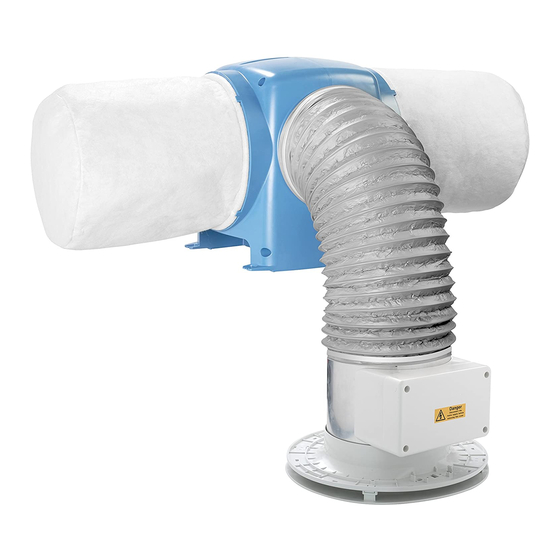
DRI-ECO-HEAT-HC
Whole House Ventilation Unit with RF Enabled Hall Control and Heating
Installation Manual
|
|
| nuaire.co.uk
Caerphilly
CF83 1NA
27. 02. 20. Document Number 671757
EMC Directive
2014/30/EU
LVD Directive
2014/35/EU
1
Advertisement
Table of Contents

Related Manuals for NuAire DRI-ECO-HEAT-HC


Summary of Contents for NuAire DRI-ECO-HEAT-HC
- Page 1 DRI-ECO-HEAT-HC EMC Directive Whole House Ventilation Unit with RF Enabled Hall Control and Heating 2014/30/EU Installation Manual LVD Directive 2014/35/EU 1.0 SAFETY INFORMATION • The provision of the electrical supply and the connection of the unit to the mains must be carried out by a qualified electrician.
-
Page 2: General Warning
Whilst the installation of the unit may be achieved by suitable persons, the provision of the electrical supply and the connection of the unit to Nuaire would always recommend a site specific risk assessment by a the mains must be carried out by a qualified electrician. - Page 3 Installation Manual DRI-ECO-HEAT-HC IMPORTANT If the diffuser cannot be repositioned, two sides of the diffuser must be closed off using the air dams supplied to encourage the air through the remaining open sides that faces at least 1.5 metres of unobstructed Isolate from power supply before removing any covers.
-
Page 4: Electrical Installation
If AV mounting is required, the kit can be purchased direct Fused Spur 2 Pole (Supplied) Isolator from Nuaire using the following code number: 771393. (By Others) 3 amp Interconnecting Lower the unit with battens (not supplied) attached onto the joists. - Page 5 Installation Manual DRI-ECO-HEAT-HC 4.1 Replacing Supply Cord 6.2 Selecting Speed If the mains supply cord to the PSU is damaged, it must be replaced When power to the unit is switched on the display will show the by the manufacturer, its service agent or similarly qualified persons in temperature control option for 2 minutes.
- Page 6 Installation Manual DRI-ECO-HEAT-HC 7.0 WIRELESS SENSORS & SWITCHES 7.3 Installing CO2 Sensor (DRI-ECO-CO2) The CO2 sensor requires a 230V power supply. Remove the front panel 7.1 Installing 4 Way Switch (DRI-ECO-4S) as per the humidity sensor and release the terminal cover via a fixing DRI-ECO-4S lug on the rear of the sensor.
-
Page 7: Maintenance
‘C’ once 5 years of use has elapsed. Put the unit into binding mode (Section 7.4). New filters can be purchased direct from Nuaire using the following part number: DRIPOS2001-FILTERKIT (five year filter). To reset the Power up sensors (insert batteries for humidity, mains for CO2). - Page 8 Installation Manual DRI-ECO-HEAT-HC 12.0 FREQUENTLY ASKED QUESTIONS While very rare, issues with newly installed units can occur. Typically these issues can be easily solved by referring to the below table. Symptom Cause Solution Ensure unit has not been NO power to the unit switched off or that the (Display is NOT lit).
Need help?
Do you have a question about the DRI-ECO-HEAT-HC and is the answer not in the manual?
Questions and answers