Table of Contents
Advertisement
1.0 SAFETY INFORMATION
•
The provision of the electrical supply and the connection of the unit to the mains must be
carried out by a qualified electrician.
•
Isolate from power supply before removing any covers. During installation / maintenance ensure
all covers are fitted before switching on the mains supply.
•
All-pole disconnection from the mains as shown in the wiring diagram must be incorporated
within the fixed wiring and shall have a minimum contact separation of 3mm in accordance with
latest edition of the wiring regulations.
•
This unit must be earthed.
•
Ducting must be securely fixed with screws to the spigot to prevent access to live parts. Duct
runs terminating close to the fan must be adequately protected by suitable guards.
•
If the supply cord is damaged, it must be replaced by the manufacturer, its service agent or
similarly qualified persons in order to avoid a hazard.
•
Precautions must be taken to avoid the back-flow of gases into the room from the open flue of
gas or other fuel-burning appliances.
•
This appliance should not be used by children or persons with reduced physical, sensory or
mental capabilities or lack of experience and knowledge, unless they have been given supervision
or instruction concerning the safe use of the appliance by a person responsible for their safety.
Children shall not play with the appliance. Cleaning and user maintenance shall not be carried
out by children.
•
In order to avoid a hazard due to inadvertent resetting of the thermal cut-out, this appliance
must not be supplied through an external switching device, such as a timer, or connected to a
circuit that is regularly switched on and off by the utility.
•
The fan unit is supplied with a fused spur. The three core mains cable from the fan unit should
be connected to a fixed wiring installation, via the spur, in accordance with current IEE wiring
regulations.
•
The CO2 sensor requires a 230V power supply. Remove the front panel as per the humidity
sensor and release the terminal cover via a fixing lug on the rear of the sensor. Refer to the
wiring diagram provided and connect the supply to the terminal box. Finally the sensor may be
mounted to the wall (screws are not provided).
•
It is important to ensure that the diffuser is NOT placed within 1 metre of a smoke alarm, if the
diffuser cannot be repositioned, two sides of the diffuser must be closed off using the air dams
supplied to encourage the air through the remaining open sides that faces at least 1.5 metres of
unobstructed area away from the smoke alarm sensor.
•
If the unit is required to switch off in the event of smoke/CO detection, alarms are available with
separate relay bases from 3rd party companies. This is a mandatory requirement for all units
installed in a 3 Storey property.
Nuaire |
Western Industrial Estate
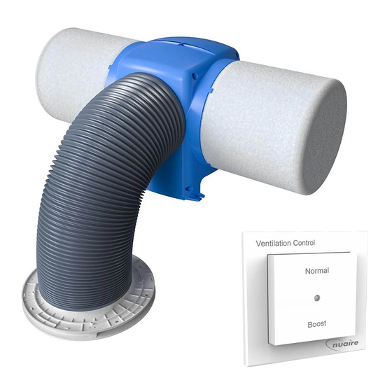
DRI-ECO-LINK-HC
Whole House Ventilation Unit
With RF Enabled Hall Control
Installation Manual
|
|
| nuaire.co.uk
Caerphilly
CF83 1NA
06. 08. 20. Document Number 671756
EMC Directive
2014/30/EU
LVD Directive
2014/35/EU
1
Advertisement
Table of Contents

Related Manuals for NuAire DRI-ECO-LINK-HC


Summary of Contents for NuAire DRI-ECO-LINK-HC
- Page 1 DRI-ECO-LINK-HC Whole House Ventilation Unit With RF Enabled Hall Control EMC Directive 2014/30/EU Installation Manual LVD Directive 2014/35/EU 1.0 SAFETY INFORMATION • The provision of the electrical supply and the connection of the unit to the mains must be carried out by a qualified electrician.
-
Page 2: General Warning
This manual contains important information on the safe and The DRI-ECO-LINK-HC fan unit includes an internal sensor to regulate appropriate assembly, transport, commissioning, operation, the fan speed according to the temperature of the loft. The internal maintenance, disassembly and simple troubleshooting of the product. -
Page 3: Filter Installation
400mm 625mm 850mm 1000mm 3.4 DRI-ECO-LINK-HC Installation SMOKE ALARMS -It is important to ensure that the diffuser is NOT placed within 1 metre of a smoke alarm. 3.4.1 Joist Hung (Standard Installation) If the diffuser cannot be repositioned, two sides of the diffuser must... -
Page 4: Electrical Installation
Nuaire using the following code number: 771393. within 50mm of other cables or each other. Lower the unit with battens (battens are not supplied by Nuaire) 4.2 Wiring Diagram attached onto the joists. Mark and drill the 12mm diameter clearance Wiring Diagram holes required in the ends of the battens. - Page 5 DRI-ECO-LINK-HC Installation Manual 6.0 WIRELESS SENSORS & SWITCH DRI-ECO-CO2 6.1 Two Way Switch Installation (DRI-ECO-2S) The switch is provided with an adhesive foam pad to allow quick and easy mounting to the wall. Alternatively the switch may be mounted to the wall using the fixing plate (screws are not provided).
-
Page 6: Speed Settings
DRI-ECO-LINK-HC Installation Manual 6.4.3 Binding Sensors for two minutes and the unit will being running at speed 6. In this time you can change the temperature setting by pressing and holding the Once the fan unit is in binding mode a switch may now be bound. -
Page 7: Maintenance
New filters can be purchased direct from Nuaire using the following part number: DRIPOS2001-FILTERKIT (five year filter). To reset the •Remaining Items can be further segregated and processed in change filter message, press and hold BOTH “up and “down”... - Page 8 DRI-ECO-LINK-HC Installation Manual NOTES Nuaire | | nuaire.co.uk 06. 08. 20. Document Number 671756 Western Industrial Estate Caerphilly CF83 1NA...
Need help?
Do you have a question about the DRI-ECO-LINK-HC and is the answer not in the manual?
Questions and answers