Advertisement
Quick Links
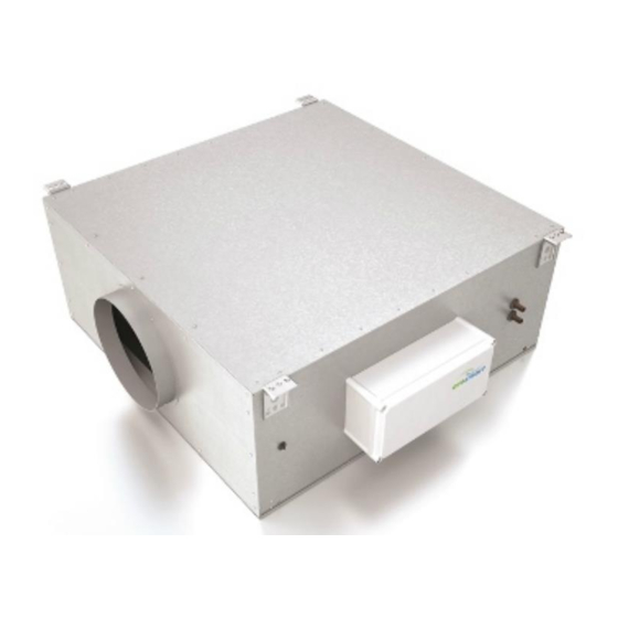
DAVE Supply Fans
The Dave range of in-line backward curve fans consisting of
9 duty sizes with a maximum of 1.1m
Units are manufactured from aluzinc, rectangular in section and have
circular rigid spigots at each end. All units are supplied with fixing
brackets designed to simplify installation.
1.0 Fan Unit Coding Descriptions
DS1A-NESH
| | |
1 2 3
1. DAVE Range
2. Supply fan
3. Case size (1-7)
4. L = LPHW Coil/valve
E = Electric heater
N = No heater
5. ES = Ecosmart control
6. No suffix = 50Hz
H = 60Hz
For systems which include supply fans with heating other than
where the BMS (0-10V) has control, the appropriate user control is
required (i.e. ES-LCD or ES-CI).
2.0 Handling
Always handle the units carefully to avoid damage and distortion.
Care must be taken to ensure any slings used for hoisting do not
damage the casing or the control module components.
Note: The weight of the unit is on the rating plate.
Figure 1: Typical lifting methods.
Slings via spreaders fitted to unit
with base frame.
Please note that above images are
examples of typical lifting methods.
Actual unit lifting plan and risks
must be assessed by competent
personnel before moving the unit.
Nuaire: A Trading Division of Polypipe Limited Western Industrial Estate Caerphilly United Kingdom CF83 1NA
DAVE Supply Fans (ES Models) 50/60Hz
For Internal and External use
Installation & Maintenance Instructions
3
/s (1100l/s).
| | |
4 5 6
Forklift.
Assembly with
base frame.
Palletised.
T: 029 2088 5911 F: 029 2088 7033 E: info@nuaire.co.uk W: www.nuaire.co.uk
3.0 Installation
Installation must be carried out by competent personnel, in
accordance with good industry practice, the appropriate authority
and in conformance with all statutory and governing regulations.
Access to the unit for maintenance is via the top or bottom lid,
therefore this should be taken into account before installation
takes place (See important note below).
Figure 2: Mounting in the vertical orientation below is not advisable
(LPHW units only).
Front Elevation
External units must not be installed at an angle over 5° from
Mounting in the vertical orientation shown above IS NOT ADVISABLE
for LPHW units due to the actuator being below the valve.
Service/Maintenance Access – Unit must be installed with a
minimum of unit depth as additional clearance i.e DS1A-NES
either allow 233mm above or below unit.
Units are supplied complete with four support mounting brackets
for quick and easy installation, either surface mounted or suspended
with drop rods.
Figure 3: Units supplied with four mounting brackets with
1 x M8 hole in each.
1
The EMC Directive
2014/30/EU
The Low Voltage
Directive
2014/35/EU
Airflow
Control
the horizontal.
18. 10. 17. Leaflet Number 671679
Advertisement

Related Manuals for NuAire DAVE Series


Summary of Contents for NuAire DAVE Series
- Page 1 Palletised. Nuaire: A Trading Division of Polypipe Limited Western Industrial Estate Caerphilly United Kingdom CF83 1NA T: 029 2088 5911 F: 029 2088 7033 E: info@nuaire.co.uk W: www.nuaire.co.uk 18. 10. 17. Leaflet Number 671679...
- Page 2 Installation, Operating and Maintenance Instructions DAVE Supply Fans (ES Models) 50/60Hz 3.0 Dimensions (mm) & Weights (ES) Supply fans Airflow When weather cover is removed from control, always replace the removed fixings. Dimensions (mm) - Supply fans Fig 4: Unit Code ‘D’...
- Page 3 Installation, Operating and Maintenance Instructions DAVE Supply Fans (ES Models) 50/60Hz Removable weatherproof cover. 4.0 Installing the Water Circuit Fig 5: It is recommended that all joints are checked for leaks when commissioning and a strainer and isolating valves are fitted (by others) for ease of maintenance.
- Page 4 Test TEST = Test button Note: A Commissioning Procedure document (leaflet No. 671153) is available on request from Nuaire Tel: 029 2088 5911. Net - the 4 IDC plug-in connectors are provided for the connection The Control Module Fig 12: of compatible sensors, manual controls and for linking the fans together under a common control.
- Page 5 Installation, Operating and Maintenance Instructions 5.0 Wiring Isolation - Before commencing work make sure that Wiring Connections for units with Ecosmart Control. the unit and Nuaire control are electrically isolated from the mains supply. Wiring for units with Electric Heater 3Kw Fig 14:...
- Page 6 Installation, Operating and Maintenance Instructions 5.0 Wiring Isolation - Before commencing work make sure that Wiring Connections for units with Ecosmart Control. the unit and Nuaire control are electrically isolated from the mains supply. Wiring for units with No Heater Fig 16:...
-
Page 7: Maintenance
Attenuation Pods Retaining Clips G4 Filter, Optional F7 Filter (Site removal) Isolation - Before commencing work make sure that the unit and Nuaire control are electrically isolated Weather Cover for control box for external installation from the mains supply. (If required) -
Page 8: Warranty
The product warranty applies to the UK mainland and in accordance with Clause 14 of our Conditions of Sale. Customers purchasing from outside of the UK should contact Nuaire International Sales office for further details. 9.0 Spares for Dave Supply fans Spare parts and replacement components are available from Nuaire Ltd. - Page 9 Where access to any part of equipment which moves, or can become electrically live are not prevented by the equipment panels or by fixed installation detail (eg ducting), then The equipment referred to in this Declaration of Incorporation is supplied by Nuaire to guarding to the appropriate standard must be fitted.
Need help?
Do you have a question about the DAVE Series and is the answer not in the manual?
Questions and answers