Table of Contents
Advertisement
Quick Links
Getting Started
Unpacking, general machine precautions, wiring,
installation
Operations & Maintenance Manual
WARNING: FOR YOUR SAFETY READ AND UNDERSTAND THIS MANUAL
PRIOR TO USING THE SAW. REVIEW ALL SAFETY RULES AND OPERATING
INSTRUCTIONS FREQUENTLY.
This manual is provided for your convenience in the use
and care of your saw. These instructions include opera-
tion, precautions, preventative maintenance and other
pertinent data to assist you in assuring long life and de-
pendable service from your saw.
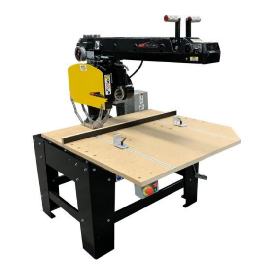
RADIAL ARM SAW
TYPE 10 - cross cut only
20" models
22.5" models
For Serial number 20190603790 for-
ward
(May 2020)
3553, 3558
3554, 3559
1
Original Saw Company
465 Third Ave SE
Britt, IA 50423 USA
PH 641-843-3868
800-733-4063
customerservice@originalsaw.com
www.originalsaw.com
Advertisement
Table of Contents

Related Manuals for Original Saw Company 3553


Summary of Contents for Original Saw Company 3553
- Page 1 Original Saw Company 465 Third Ave SE Britt, IA 50423 USA PH 641-843-3868 800-733-4063 customerservice@originalsaw.com www.originalsaw.com Getting Started Unpacking, general machine precautions, wiring, installation Operations & Maintenance Manual WARNING: FOR YOUR SAFETY READ AND UNDERSTAND THIS MANUAL PRIOR TO USING THE SAW. REVIEW ALL SAFETY RULES AND OPERATING INSTRUCTIONS FREQUENTLY.
-
Page 2: Service Record
Service Record Serial Number_____________________ Date Purchased ______________ Date Service Performed... -
Page 3: Table Of Contents
We will cover the cost of the defective part and ground shipping. If a replacement part is sent under warranty the defective part must be returned to Original Saw Company or you will be charged for the replacement. The part must also be accompanied by a return goods authorization number. This number can be obtained by calling customer service at 1-800-733-4063. -
Page 4: Power Tool Safety
13. REMOVE ADJUSTING KEYS AND WRENCHES. Make it a habit to ensure keys and adjusting wrenches are removed prior to starting tool. 14. USE RECOMMENDED ACCESSORIES. Consult your distributor or Original Saw Company for recommended accessories. Using improper accessories may cause hazards. -
Page 5: Preventative Maintenance
Preventative Maintenance Modifications: − • Any modifications to the machine including in- Original Radial Arm Saws are designed to provide corporation into an assembly, addition of integrat- you with precision cutting with a minimal amount ed feeds or other changes are the responsibility of of maintenance. - Page 6 MANTAINENANCE RECORDS Use this space to record service or use Preventative Maintenance … Continued page 2 for a more detailed recording for your Original radial arm saw. − • After many years of use your saw may need replacement parts. If any of the following wears out all others listed should be checked also.
-
Page 7: Symbols / Decals
SYMBOLS / DECALS Denotes risk of injury, loss of life, Denotes hearing and eye damage to the tool in case of not protection required. observing the instructions in this manual. Denotes guards required to be Denotes risk of electrical shock. in place. -
Page 8: Decal Locations
SYMBOLS / DECALS Caution # 3 denotes a pinch point between bevel stop and roller head Arm: # 5 denotes hand entanglement - General Caution with spring return cable. ARM: - Caution , do no oper- ate with safety stop re- moved Danger # 2 Hazardous... -
Page 9: Saw Components And Controls
Components and Controls (on front of frame) controls & components locations A. Miter Latch Handle B. Arm Clamp Handle C. Elevating Control Handle D. Miter Scale E. On/Off Switch F. E-stop Caution G. Adjustable Arm Stop (not shown E-stop yellow Surround attaches on this side of the arm) back plate H. -
Page 10: Product Specifications
PRODUCT SPECIFICATIONS 20 inch / 508 mm 3 phase 3553 / 3558 SD Series Standard equipment: Machine, Complete upper and lower blade guard, carriage return attachment wrench kit, magnetic starter with overload/ low voltage protection, low voltage start/stop station, oversized MDF table... - Page 11 Machine, Complete upper and lower blade guard, carriage return attachment wrench kit, magnetic starter with overload/ low voltage protection, low voltage start/stop station, oversized MDF table top, heavy gage steel frame and leg stand with leg braces GENERAL SPECIFICATIONS Manufacturer ……………………………………………….. Original Saw Company Electrical drawing ………………………………………….. 121239-75 Enclosure rating …………………………………………… IP65 Material to be cut ……………………………………………...
-
Page 12: Ansi Conformance
• Maximum size of material 3553/3558-03-208/230, 3553/3558-03-460, 3553/3558-03- 575/600, 3554/3559-03-208/230, 3554/3559-03-460, • 3553/ 3558 width 23 / 31” depth 6.25” 3554/3559-03-575 • 3554/ 3559 width 23 / 31” depth 8” Original Saw declares that these power tools have been de- Residual Risks signed in compliance with ANSI Machine Standards 01.1-... - Page 13 SAW ASSEMBLY AND INSTALLATION UNPACKING YOUR SD SERIES SAW Your Super Duty series saw system has been completely assembled, tested, and then partially disassembled. The shipment of your saw contains the following items: • The Super Duty Series Saw, (4) frame legs, arbor wrenches, allen hex wrench kit, hardware to attach legs.
-
Page 14: Arbor Rotation
SAW ASSEMBLY AND INSTALLATION Check Arbor Rotation (3 Phase Only) Check arbor rotation with arbor nut and arbor collars removed. Open line disconnect to the saw to remove arbor nut and collars, close the line disconnect and start saw. The rotation of the ar- bor must be clockwise as indicated on the arrow on the nameplate. -
Page 15: Saw Assembly And Installation
SAW ASSEMBLY AND INSTALLATION Saws equipped with Variable Frequency Drives (VFD) Connecting Electrical Current The motor is properly connected to the VFD at the factory for operation on the electrical voltage specified. Make sure incoming voltage from your power supply conforms to the voltage specified on the cover of VFD enclosure. -
Page 16: Electrical Connections
Electrical Connection— Recommend Copper Wire Sizes (A.W.G.) To obtain maximum efficiency from your saw motor, the feeder wire from the power source to the machine should comply with the table below. Always follow NEC rules and guidelines along with local AHJ. Note: Always check arbor shaft rotation before installing blade, arbor nuts, or collars. -
Page 17: Blade Mounting
SAW ASSEMBLY AND INSTALLATION !Caution disconnect / lock out power source before mounting blade! !!! CAUTION !!! FOR ILLUSTRATION PURPOSES ONLY , THE GUARDS HAVE BEEN REMOVED FOR THE PHOTOS USED IN THIS MANUAL. IN ACTUAL USE BOTH UPPER AND LOWER GUARDS MUST REMAIN IN PLACE FOR SAFE CUTTING OPERATION. -
Page 18: Operating Instructions
Operating Instructions General Safety Precautions 1. Be sure the blade rotates clockwise when facing the saw from the left side. Blade must rotate to the front of the saw. 2. Be sure all clamp handles are tight before turning motor on. 3. - Page 19 Operating Instructions Alternate Guide Strip Positions Your saw was assembled with the guide strip in the most frequently used position on the work table (see figure 3). The guide strip may be moved to alternate positions to accommodate varying uses. Moving the guide strip behind the spacer board will allow for maximum cross cutting capabilities.
- Page 20 Operating Instructions standard manual clamp / material stop …. continued During operations where the arm is swung left or right could put the clamp in the path of the blade. If this is going to happen simply add scrap board that will allow the clamp to be moved further out on the table and clear the blade path.
- Page 21 Operating Instructions Raising and Lowering the Arm When the column clamp handle is pulled for- ward, the elevating crank can be used to raise or lower the arm. Using the elevating scale and the indicator on the elevating crank, the desired depth of cut can be adjusted.
- Page 22 Operating Instructions Cross Cutting Lock the arm in the 0 position. Place the ma- terial securely against the guide strip– keep hands well away from the blade. Draw the saw blade across the material. After the cut has been completed return the blade behind the guide strip.
-
Page 23: Alignment And Adjustments
Maintenance Adjustments and Alignments Caution! Disconnect and lockout power supply before making any adjustments Your saw has been completely assembled, aligned and tested at the factory...then partially disas- sembled for shipment. Handling during shipment may cause some misalignment and the following information will enable you to correct any cutting inaccuracy you discover. - Page 24 Maintenance Adjustments and Alignments Caution! Disconnect and lockout power supply before making any adjustments or alignments. Adjustment of the Rollerhead to Arm Accurate work cannot be done if the roller bearings of the motor carriage are not in proper adjustment. When play develops between the rollerhead and the arm the following adjustment is required: 1.
-
Page 25: Parts Diagram And Listings
Maintenance Adjustments and Alignments Caution! Disconnect and lockout power supply before making any adjustments or alignments. Adjustment of Table Top Parallel to Arm The arm tracks must be parallel to the tabletop at all points. This assures uniform depth of cut, especially when dado cutting. - Page 26 Maintenance Adjustments and Alignments To Square Saw Blade with the Table Top Make sure the tabletop is level and place a steel square against the side of the blade; the square should be against the gullets and not the teeth of the blade. If the blade is not square to the tabletop: 1.
- Page 27 Maintenance Adjustments and Alignments Caution! Disconnect and lockout power supply before making any adjustments or alignments. Adjustment of Miter, Bevel and Swivel Latches If a loose condition ever develops between the miter, bevel or swivel latches and their respective adjusting screws, refer back to the following sections for adjustment.
- Page 28 Maintenance Adjustments and Alignments Bevel Stop Rod The bevel stop rod (A) is a device mounted on the rollerhead to prevent the blade from contacting the base when the bevel cuts are being made; particular- ly with 20” blades. A socket head cap screw (B) locks the rod into position.
- Page 29 Changing the Motor Voltage WARNING—DISCONNECT AND LOCKOUT POWER BEFORE SERVICING If your machine requires a different voltage, follow the instructions below. The motor will need to be rewired according to the diagrams below. The thermal overloads must be reset or replaced with the proper pieces to maintain thermal motor protection. Motor lead wiring diagram Instructions for Changing the Motor Voltage Disconnect and lockout power–...
- Page 30 VFD Wiring Diagram WARNING—DISCONNECT AND LOCKOUT POWER BEFORE SERVICING VFD Arbor Rotation This is usually set from the factory but in certain cases if rotation needs switched, you can change any 2 of the motor lead wires. Changing incoming power leads will not change rotation.
-
Page 31: Troubleshooting
Alignment Guide for Accurate Cutting The following guide is provided for your convenience. A saw that is not properly adjusted will not yield the desired accuracy and quality of cut. It should be noted any adjustment made will effect another, therefore it is best to perform all of the adjustments when correcting any one problem. PROBLEM POSSIBLE CAUSE SOLUTION... - Page 32 PROBLEM POSSIBLE CAUSE SOLUTION Saw blade or dado blades tend to − − Saw blade is heeling Make heel adjustment (p. 28) push lumber to one side when cross − − Column too loose in base Make proper adjustment (p. 24) cutting −...
- Page 33 ELECTRICAL TROUBLE-SHOOTING GUIDE CAUTION—HIGH VOLTAGES ARE DANGEROUS—BE SURE POWER IS OFF AND LOCKED OUT WHEN INSPECTING OR REPAIRING MOTOR OR CONTROLS TROUBLE POSSIBLE SUGGESTED REMEDY CAUSE Power line not connected to Correct power wiring. See wiring diagram inside mag- cable. netic starter box.
- Page 34 Intentionally left blank...
- Page 35 For parts or service please contact Original Saw for the dealer nearest you. 465 Third Ave SE P.O. Box 331 Britt, IA 50423 PH 800/733-4063 641-843-3868 FX 641 / 843-3869 E-mail customerservice@originalsaw.com www.originalsaw.com Printed in the USA © The Original Saw Company 03/2020 Super Duty Series Type 10...
Need help?
Do you have a question about the 3553 and is the answer not in the manual?
Questions and answers