Table of Contents
Advertisement
Getting Started
Unpacking, general machine precautions, wiring,
installation, preventative maintenance.
Operations & Maintenance Manual
This manual is provided for your convenience in the use
and care of your saw. These instructions include opera-
tion, precautions, preventative maintenance and other
pertinent data to assist you in assuring long life and de-
pendable service from your saw.
RADIAL ARM SAW
TYPE 5 - cross cut only
14" models 3531-01, 3536-01, 3531-03, 3536-03
16" models 3541, 3546
For Serial number 20190603790 forward
(July 2019)
WARNING: FOR YOUR SAFETY READ AND
UNDERSTAND THIS MANUAL PRIOR TO
USING THE SAW. REVIEW ALL SAFETY
RULES AND OPERATING INSTRUCTIONS
FREQUENTLY.
1 1
Original Saw Company
465 Third Ave SE
Britt, IA 50423 USA
PH 641-843-3868
800-733-4063
customerservice@originalsaw.com
www.originalsaw.com
Advertisement
Table of Contents

Subscribe to Our Youtube Channel
Related Manuals for Original Saw Company 3531-01


Summary of Contents for Original Saw Company 3531-01
- Page 1 RULES AND OPERATING INSTRUCTIONS FREQUENTLY. RADIAL ARM SAW TYPE 5 - cross cut only 14” models 3531-01, 3536-01, 3531-03, 3536-03 16” models 3541, 3546 For Serial number 20190603790 forward (July 2019)
-
Page 2: Table Of Contents
We will cover the cost of the defective part and ground shipping. If a replacement part is sent under warranty the defective part must be returned to Original Saw Company or you will be charged for the replacement. The part must also be accompanied by a return goods authorization number. -
Page 3: Service Record
Service Record Serial Number_____________________ Date Purchased ______________ Date Service Performed... -
Page 4: Power Tool Safety
13. REMOVE ADJUSTING KEYS AND WRENCHES. Make it a habit to ensure keys and adjusting wrenches are removed prior to starting tool. 14. USE RECOMMENDED ACCESSORIES. Consult your distributor or Original Saw Company for recommended accessories. Using improper accessories may cause hazards. -
Page 5: Use / Ansi Conformity
Use and ANSI Declaration ANSI-Declaration of conformity Intended Use of Machine 3531-01-230, 3536-01-230, 3531-03-208/230, 3536-03- − Machines for Wood and plastic cutting only 208/230, 3531-03-460, 3536-03-460, 3531-03-575/600, − Maximum size of material 3536-03-575/600 − 3531-01 3531-03 width 16” / 400 mm Original Saw declares that these power pools have been thickness 4 1/8 ”... -
Page 6: Use / Preventative Maintenance
− Lock out Tag out procedures to be adopted during all and legible, if they are damaged order replacements maintenance. − from Original Saw Company. Lock out Tag out procedures to be observed when − changing blade − Monthly / Bi-Monthly —Every 160 hours of use:... -
Page 7: Symbols / Decals
SYMBOLS / DECALS The following symbols are used throughout this manual: Denotes risk of personal injury, loss of life or damage to the tool in case of non-observance of the instructions in this manual. Denotes risk of injury, loss of life, Denotes hearing and eye damage to the tool in case of not protection required. -
Page 8: Decal Locations
Symbols / Decals Arm: General Caution Guard: # 4 Hazard Rotating blade # 6 Hearing and eye protection # 7 Guards required to be in place rotation direction use blades rated at 3450 rpm Arm: right side Do not operate with safety stop removed Magnetic Starter: Risk of electrical shock... -
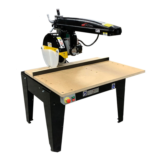
Page 9: Saw Components And Controls
Components and Controls !!! CAUTION !!! BOTH UPPER AND LOWER GUARDS MUST REMAIN IN PLACE FOR SAFE CUTTING OPERATION. Control Locations A. Miter Latch Handle B. Arm Clamp Handle C. Elevating Control Handle D. Miter Scale E. On/Off Switch F. Adjustable Arm Stop G. -
Page 10: Product Specifications
14” / 350mm 3531-01, 3536-01, 3531-03, 3536-03 16” / 400mm 3541, 3546 Standard equipment: Machine, Complete upper and lower blade guard, carriage return at- tachment wrench kit, magnetic starter with overload/ low voltage pro- tection, low voltage start/stop station, oversized MDF table top, heavy gage steel frame and leg stand. -
Page 11: Electrical Connections
11 11... -
Page 12: Saw Assembly And Installation
SAW ASSEMBLY AND INSTALLATION UNPACKING YOUR HEAVY DUTY SERIES SAW Your Heavy Duty series saw system has been completely assembled, tested, and then partially disassembled. The shipment of your saw contains the following items: • The Heavy Duty Series Saw, (4) frame legs, arbor wrenches, allen hex wrench kit, hardware to attach legs. -
Page 13: Arbor Rotation
SAW ASSEMBLY AND INSTALLATION … continued Check Arbor Rotation (3 Phase Only) Check arbor rotation with arbor nut and arbor collars removed. Open line disconnect to the saw to remove arbor nut and col- lars, close the line disconnect and start saw. The rotation of the arbor must be clockwise as indicated on the arrow on the nameplate. - Page 14 SAW ASSEMBLY AND INSTALLATION … continued General Safety Precautions Be sure the blade rotates clockwise when facing the saw from the left side. Blade must rotate to the front of the saw. Be sure all clamp handles are tight before turning on motor. Keep the blade sharp and properly set.
-
Page 15: Blade Mounting
SAW ASSEMBLY AND INSTALLATION … continued Electrical Precautions Be sure machine is properly grounded. Do not attempt to operate saw on any voltage other than the one designated. Use correct size time delay fuses to protect incoming current. If it takes more than 3 seconds to reach maximum speed with a standard blade, turn the saw off. ( See trouble shooting on page 26 of this manual). -
Page 16: Operating Instructions
Operating Instructions Moving the Arm Horizontally and Vertically The elevating crank is used to raise or lower the arm to accommodate cutting operations (see below left). Do not adjust the height of the saw with the base / clamp handle tight (see page 9 for location) or while the motor is running. Change the posi- tion of the arm for miter cutting is done by pulling the arm clamp handle (A) forward and lifting the miter latch handle (B). - Page 17 Operating Instructions Rip Cutting - (rip kit required and is Optional ) In Rip—Out Rip When ripping the arm should be locked in a cross cut position. Pull the motor to the end of the arm. Release the yoke clamp handle by pulling forward and lift the rip index pin.
-
Page 18: Alignment And Adjustments
Operating Instructions Rip Cutting - (rip kit required and is Optional ) Figure 1 In Rip—Out Rip To set up guard for ripping start by swiveling the carriage into the in rip or out rip position. Then using a wrench loosed the studs that run through the inner guard ring retainers on both the front and back retainers as in figure #1 and Figure #2. - Page 19 Bevel Cutting Lock the arm in the cross cutting position. Raise the motor by rotating the elevation crank. Release the bevel clamp and the bevel index pin and tilt the motor in the yoke. The bevel angle is shown on the bevel scale.
- Page 20 Maintenance Adjustments and Alignments Caution! Disconnect and lockout power supply before making any adjustments or alignments. Your saw has been completely assembled, aligned and tested at the factory...then partially disassembled for shipment. Han- dling during shipment may cause some misalignment and the following information will enable you to correct any cutting inaccuracy you discover.
- Page 21 Adjustment of the Roller head to Arm (cont’d) Insert socket wrench into bottom of bearing shaft (B) and turn until the bearing touches the arm track on both top and bottom tracks. Repeat for both shafts. Bearings should be tightened only so that they roll and do not slide. Replace the end cap and return saw to normal position.
- Page 22 To Square Saw Blade with the Table Top Pull the saw to middle of table and lock into place. Make sure the tabletop is level and place a steel square against the side of the blade; the square should be against the gullets and not the teeth of the blade.
- Page 23 Adjusting Crosscut Travel Parallel to Arm Tracks (continued) After making the left and right adjustments, tilt the motor to a 45 bevel cutting position and make cuts in a 2” x 4” piece of material. If tooth marks appear the motor is too high or low in the rear yoke: If marks are made on the bottom side of material: Release the bevel clamp handle.
-
Page 24: Troubleshooting
Changing the Motor Voltage WARNING—DISCONNECT AND LOCKOUT POWER BEFORE SERVICING If your machine requires a different voltage, follow the instructions below. The motor will need to be rewired according to the diagrams below. The thermal overloads must be reset or replaced with the proper pieces to maintain thermal motor protection. Motor lead wiring diagram instructions for Changing the Motor Voltage Disconnect and lockout power–... - Page 25 1 phase wiring diagram WARNING—DISCONNECT AND LOCKOUT POWER BEFORE SERVICING If your machine requires a different voltage, follow the instructions below. The motor will need to be rewired according to the diagrams below. The thermal overloads must be reset or replaced with the proper pieces to maintain thermal motor protection. Motor lead wiring diagram 25 25...
- Page 26 Alignment Guide for Accurate Cutting The following guide is provided for your convenience. A saw that is not properly adjusted will not yield the desired accuracy and quality of cut. It should be noted any adjustment made will effect another, therefore it is best to perform all of the adjustments when correcting any one problem. PROBLEM POSSIBLE CAUSE SOLUTION...
- Page 27 PROBLEM POSSIBLE CAUSE SOLUTION Saw blade or dado blades tend to − − Saw blade is heeling Make heel adjustment (p. 20) push lumber to one side when cross − − Column too loose in base Make proper adjustment (p. 18) cutting −...
- Page 28 ELECTRICAL TROUBLE-SHOOTING GUIDE CAUTION—HIGH VOLTAGES ARE DANGEROUS—BE SURE POWER IS OFF AND LOCKED OUT WHEN INSPECTING OR REPAIRING MOTOR OR CONTROLS TROUBLE POSSIBLE SUGGESTED REMEDY CAUSE Power line not connected to Correct power wiring. See wiring diagram inside mag- cable. netic starter box.
- Page 29 465 Third Ave SE P.O. Box 331 Britt, IA 50423 PH 800/733-4063 641-843-3868 FX 641 / 843-3869 E-mail customerservice@originalsaw.com www.originalsaw.com Printed in the USA © The Original Saw Company 08/2019 HD Series Type 6 (Updated electrical connections page 11, 1.23.2020) 29 29...
Need help?
Do you have a question about the 3531-01 and is the answer not in the manual?
Questions and answers