Advertisement
W
I
N S T A L L A T I O N
This manual covers installation of the wireless weather station. Some fea-
tures discussed (such as barometric pressure and humidity) are only avail-
able with the Wireless Weather Monitor II
installation with the solar power option, which may not be included in
your wireless weather station. Other manuals included with the station
cover the operation and maintenance of the console and sensors.
C
OMPONENTS
The wireless weather station includes the following components. Please
make sure you have everything you need before beginning.
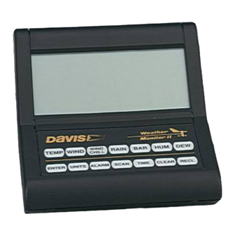
Weather Station Console
Power Adapter
Rain
Collector
2nd Power Adapter
(not supplied with
solar-powered
stations)
3 Volt Lithium
Transmitter Battery
(not supplied with
solar-powered
stations)
Product # 7425W, 7425WM, 7425WS, 7425WSM, 7440W, 7440WM, 7440WS, 7440WSM
W
I R E L E S S
M
Extension
Tube
Sensor Array
E A T H E R
A N U A L
®
. This manual also shows
Anemometer
5/16" Flat Washers
5/16" Lock Washers
5/16" Hex Nuts
Wind Cups
This hardware
comes installed
on Sensor Array:
#12 x 1-1/2"
Pan Head Screw
#12 Lock Washer
#12 Hex Nut
Field Case
S
T A T I O N
5/16" x 1-1/2"
U-Bolt
1-1/8"
Saddles
5/16" x 3"
Lag Screws
5/16"
Flat Washers
Cable
Tie
#8 x 3/4"
Pan Head Screws
(for mounting Console)
Debris Screen
(place inside
Allen
Rain Collector Cone
Wrench
after installation)
Advertisement
Table of Contents

Related Manuals for DAVIS Weather Monitor II


Summary of Contents for DAVIS Weather Monitor II
- Page 1 This manual covers installation of the wireless weather station. Some fea- tures discussed (such as barometric pressure and humidity) are only avail- able with the Wireless Weather Monitor II installation with the solar power option, which may not be included in your wireless weather station.
-
Page 2: Tools And Materials Needed
OOLS AND ATERIALS In addition to the components listed above, you may need some of the follow- ing tools and materials. Flat-Bladed Screwdriver Phillips Screwdriver Adjustable Wrench Wire Cutter or Scissors Pencil or Other Pointed Object NSTALLATION TEPS This manual takes you through the step-by-step process of installing your weather station. -
Page 3: Getting Started
SSEMBLING THE Getting Started Follow the steps below to assemble your station. At various stages of this assembly, you will be advised to test the system to ensure proper functioning. 1. Detach and remove the extension tube from the support tube by cutting the two black cable ties. - Page 4 4. Prepare the rain collector for use. Detach the black rain collector cone from its base by rotating the cone counter-clockwise until its latches line up with the latch openings in the base and then lift the cone off. (The cone fits tightly and may require extra pres- sure to remove it the first time.) Carefully cut and remove the black cable tie which holds the bucket in place during shipping.
- Page 5 6. If all is well, re-attach the mounting base as shown below. Use the standard setup unless you have the optional WeatherLink. Power Adapter Power Adapter Note: As illustrated above, if you are using the WeatherLink in addition to the SensorLink Receiver, you will need to position the receiver outside the mounting base.
-
Page 6: Lithium Battery
If you have a non-solar-powered system, decide whether you want to install the power adapter OR the lithium battery (the two will NOT work in tan- dem or as backup). Davis recommends the battery to ensure power during storms. If used as the primary power source, one fresh lithium battery should provide about six months of service. - Page 7 For roof mounting, and for ease of installation in other locations, we recommend using the optional Mounting Tripod (contact Davis for more information). As you position your console, be aware of possible interference from cordless phones and other items.
- Page 8 ESTING ROPOSED Test your proposed console and sensor locations to ensure successful data transmission. 1. Temporarily place the sensor array where you plan to mount it. 2. Apply power to the sensor array (see step 7 on page 6). 3. Set dip switch #4 on the transmitter to the TEST position, as shown below. This puts the transmitter in Test Mode —the Indicator LED will flash to indi- cate that the sensor unit is transmitting.
-
Page 9: Dip Switch Settings
ID code. Use the default setting unless you have another Davis wireless weather station operating nearby which you want to work separately from the new system. The dip switch settings for the eight possible codes are shown below. - Page 10 Silent Operating Mode Dip switch #4 on the receiver allows you to set the console to either emit audi- ble warnings or stay silent. In Silent Mode, the console does not beep to indicate problems such as low battery or poor reception. The factory sets Silent Mode off as the default so that the console will warn you when problems occur.
-
Page 11: Mounting The Sensor Array
12 for instruction). For roof mounting, and for ease of installation in other locations, we recom- mend using the optional Mounting Tripod (contact Davis for information). Please refer to the tripod manual for tripod installation instructions. Note: If mounting on a roof, tower, or other elevated structure without the tripod, be sure to consider the effects of wind loading and vibration and design the installation accordingly. - Page 12 Important: Mount Station Pointing South The station’s wind direction is calibrated as if the horizontal part of the ane- mometer arm were pointing south. To take advantage of the station’s preset wind direction, be sure to mount your station with the anemometer arm pointing south.
-
Page 13: Mounting The Console
Securing the Sensor Array After mounting the sensor array, secure the sensor array to the extension tube as shown below. Nuts Lock Washers Powering the Sensor Array To re-apply power to the sensor array, refer to the instructions on page 6. OUNTING THE ONSOLE 1. -
Page 14: Troubleshooting
8). If two beeps or more are heard in a 2.5-second interval, then another Davis wireless system may be operating nearby on the same ID (or a cordless phone may be operating within 10 feet of the receiver). Try changing to a different ID code on both the console and the sensor array (or try moving the phone). -
Page 15: Specifications
Power Input Options Battery power: CR-123 3- volt lithium or equal; one or two cells AC power adapter: Davis adapter or equal (5 to 10 VDC output @ 1mA) Solar Power Kit: Davis solar charger (Optional, product #7709. Offers the added capability of replacing current power with a rechargeable solar power supply.) -
Page 16: Fcc Part
Rev. F Manual (7/16/99) Controlled online: Weather Manuals/Consoles/Wireless System/Wireless © Davis Instruments Corp. 1998. All rights reserved. Weather Monitor II, Weather Wizard III, WeatherLink and SensorLink are trademarks or registered trademarks of Davis Instruments Corp. EGISTRATION 3465 Diablo Avenue, Hayward, CA 94545-2778 510-732-9229 •...
Need help?
Do you have a question about the Weather Monitor II and is the answer not in the manual?
Questions and answers